GV75W User Manual
TRACGV75WUM001
‐ 12 ‐
3.6.
Digital Output
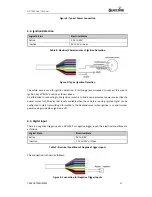
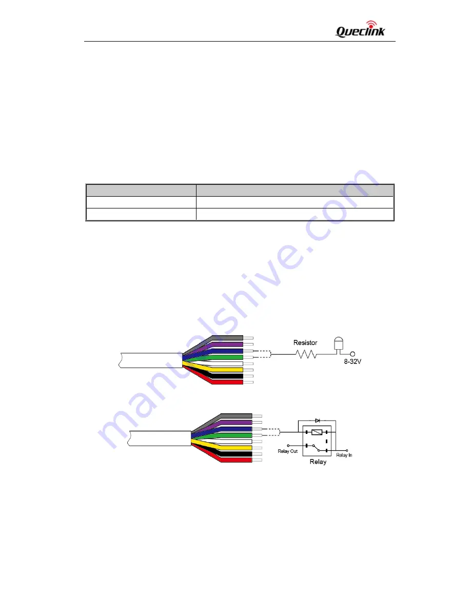
The outputs are Open‐Drain type with no internal pull‐up resistor which can be used to control a relay.
It means that the user has to connect a pull‐up resistor or a relay coil between the output pin and
any positive voltage (32V max) to generate correct output. Each output can drive a continuous
current of 0.15A.
The green wire is low side 150mA max, and the blue wire is low side 150mA max with latch.
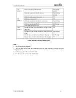
The electrical conditions are shown in the following table:
Table 8: Electrical Conditions of Digital Outputs
Note:
The relay output can be latched by the software, so even if the GV75W is restarted or powered down
in some cases, the relay output will not change. To use the latch function, the main power and backup
battery should be connected. Otherwise the relay will always be in normally closed state.
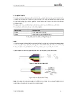
Digital outputs are used for cutting/restoring GND. The connections are shown below.
Figure 5: Connection to Drive an LED
Figure 6: Connection to Drive a Relay
Note:
All outputs are internally pulled up to PWR pin by a diode. So no external flyback diode is
needed when the output is connected to an inductive load.
Logical State
Electrical State
Enable
<1.5V, drive current is 0.15A
Disable
Open or the pull‐up voltage (max 32V)


