Operation - Safety Guidelines
Before use, always check the mover for any damage.
When towing or moving the caravan please be aware, at all times, that ground clearance is reduced by 50mm
when the Mover has been fitted.
To maintain signal strength, always make sure that, during manoeuvring, the distance between the remote
control and the caravan does not exceed 5 metres.
DO be aware that the mover increases your caravan or trailer weight. So this reduces the payload of the
caravan.
DO always make sure that the rollers are fully disengaged from the tyres when the mover is not in use. This is
better for the tyres and for the mover.
DO always make sure that the rollers are fully disengaged before towing/moving the caravan by vehicle or
manpower. This can damage the tyres, mover and the towing vehicle.
DO always make sure that after you have finished using the Mover, the Battery Power Isolation Switch (29) is
switched off and the key is removed and stored in a safe place (out of reach of children or other
unauthorised people).
DO always make sure that the remote control is stored in a safe place (out of reach of children or other
unauthorised people).
DO always apply the handbrake after manoeuvring, before disengaging the drive rollers from the tyres.
DO always ensure that children and pets are kept well out of the way during operation.
DO NOT rely on the mover to act as a brake.
DO NOT exceed the total Safe Working Load (SWL).
DO NOT make any modifications on the caravan mover (mechanical or electronically). This can be very
dangerous! No warranty claim will be accepted and we cannot guarantee the function of the mover if any
modifications are made. We will not be liable for any damage whatsoever caused as a result of incorrect
installation, operation or modification.
Operation - Remote Control Handset
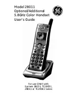
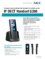
The Remote Control handset (1) is powered by three ‘AAA’ 1.5V batteries, and is activated by double-pressing the power
button (Fig.1A). Once activated the green LED (Fig.3H) will illuminate and the directional controls can now be used. If the
handset has not been used for a period of 60 seconds then it will automatically switch itself off.
Fig.1
A = On (press button twice within one second, green LED (Fig.3H) illuminates)
B = Caravan forwards (both wheels rotate in forwards direction)
C = Caravan reverse (both wheels rotate in reverse direction)
D = Caravan left forwards (right wheel rotates in forwards direction)
E = Caravan right forwards (left wheel rotates in forwards direction)
F = Caravan left reverse (right wheel rotates in reverse direction)
G = Caravan right reverse (left wheel rotates in reverse direction)
In addition, the ‘left forward’ (1D) and ‘right reverse’ (1G) buttons or ‘right forward’ (1E) and ‘left reverse’ (1F) buttons
may be pressed at the same time to turn the caravan around on its own axis (without moving forward or backward).
Note: this function is disabled when the electronics are in twin-axle mode.
When pressing a directional button on the handset, the mover will start slowly, normal speed will be reached within 2.5
seconds.


