


Quartz Q16/Q32 System Manual
18 May 2004
Issue 5.00
Page 6
INSTALLATION
Introduction
This section describes how to install your Q16/Q32 system with the minimum of fuss and time. The
system has been designed with the aim of being simple to install.
Unpacking
Carefully remove the equipment from the boxes and check it against the Packing List. This shows
what items have been shipped against your order and includes all options. Any error should be
reported to your supplier immediately. After you have unpacked the equipment please save all the
packing material as this could be useful in the future if the unit needs to be returned for maintenance.
Check each item supplied for transit damage. Any damage should be reported in detail to your
supplier. You must state the serial number of the unit (to be found on the rear or side of each unit).
Check that power cords supplied are suitable for your country and that the equipment has been set to
the correct mains (line) voltage. Note that standard remote panels are mains powered and must also
be checked. Instructions are to be found later in this section on how to change the voltage.
Do NOT change any DIP switch or rotary switch settings at this stage as these will have been
correctly set before leaving the factory.
Physical Installation
All frames are designed for mounting in standard 19" equipment racks. When preparing for
installation bear in mind that the modules are plugged in from the front and extra space is required for
the modules to mount on an extender module. You should allow at least 800mm clearance at the front
for maintenance.
The depth of most router frames is 485mm plus connectors from the front of the equipment rack. In
addition allowance must be made for the high numbers of cables to be installed at the rear of the
frame.
Power dissipation in most frames is relatively low and cooling is achieved by natural convection
through the sides of the frame. In the interests of long term reliability it is advisable, where possible, to
leave a 1U gap or to fit a unit with a depth of less than 200mm above every fourth 1U or 2U frame.
The
Q16 & Q32 Serial Digital Video Routers
are fan cooled, drawing cool air in from the front of the
frame and expelling it to the left-hand and right-hand sides of the frame
.
It is important that the
ventilation slots in the lid of this unit are not obstructed; it is perfectly acceptable to install a control
panel or another shallow unit immediately above the unit but not another frame.
The
Q32 Analogue Audio Router
is fan cooled, drawing cool air in from the front of the frame and
expelling it at the left-hand and right-hand sides of the frame.
In all cases,
it is important to keep the apertures clear of obstructions
e.g. cables.
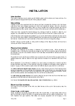
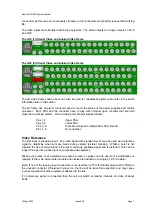
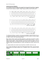
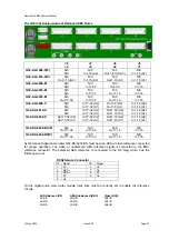
Electrical Connections
The views of the rear panel of the Q16 and Q32 frames at the end of this section show the
connections.
Video Inputs and Outputs
These connections are made using standard video 75
Ω
coaxial cable. A high quality cable such as
PSF1/2 (TF3255) or PSF1/3 (TF3304) or equivalents should be used for optimum performance. It is
both important and good practice that cables are properly supported and not
hanging
on the


