


Quartz Q16/Q32 System Manual
18 May 2004
Issue 5.00
Page 30
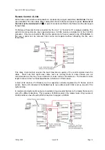
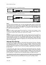
The 1U Q16 frame is shown in schematic form below
Inputs 1-16,
outputs 1-16, and
processor
(PC-273 / PC-215)
PS-0009
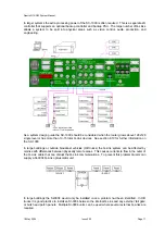
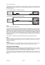
The 2U Q32 frame is shown in schematic form below
Inputs 1-32,
outputs 1-32, and
processor
(PC-273 / PC-215)
PS-0010
Main PSU
PS-0010
Backup PSU
Inputs
The video inputs are terminated in 75
Ω
. The serial video signal passes through an input receiver
circuit either built on to the main module or to a plug-in SIMM socket so that extra channels can be
added in the field. These circuits provide equalisation for losses, mainly at high frequencies, to serial
video signals that have travelled down long cables. This equalisation is varied automatically to suit
the length and type of video cable used.
Matrix
On the Q16 system a single crosspoint chip selects the 16 inputs to the 16 outputs. This is
mounted on a small PCB assembly. On the Q32 system a similar assembly replaces this
containing two crosspoint chips to select the 32 inputs to the 32 outputs.
Outputs
The output circuit is also built onto a plug-in SIMM. It contains a Phase Lock Loop (PLL) that locks an
oscillator to re-clock the signal so that the correct pulse widths and timings are regenerated. The
circuit automatically copes with any of the standards mentioned above. The PLL is designed to
minimise the jitter on the signal. A non-reclocked version of the output SIMM is available where lower
cost is required. The output amplifiers are designed to drive 75
Ω
video cables. The Q16 and Q32
product have single outputs.
Analogue Video Routing
The Q16 16x16 video matrix is based on a single matrix module that holds the inputs, crosspoints,
and outputs, and is available in various sizes up to 16x16. All circuitry is ‘surface mount’ and there
are no adjustments for gain or HF. The unit has a bandwidth of 100MHz. Two sets of jumper links
are fitted to allow blocks of 8 inputs to be set for
Restored
(PAL or Y component) or
DC Coupled
(U
and V components). The frame is 1U high. Dual power supplies are
not
supported in this frame, see
the Q32 product.
The Q32 32x32 video matrix is based on a single matrix module that holds the inputs, crosspoints,
and outputs, and is available in various sizes up to 32x32. All circuitry is ‘surface mount’ and there
are no adjustments for gain or HF. The unit has a bandwidth of 100MHz. Four sets of jumper links
are fitted to allow blocks of 8 inputs to be set for
Restored
(PAL or Y component) or
DC Coupled
(U
and V components). The frame is 2U high and dual power supplies can be fitted in this frame.
The crosspoints are switched during the vertical interval using the reference input signal and both
units have jumper links to set the TV switching line (line 6 to 10) and to select field or frame rate
switching. If a reference input is not connected then the unit free runs i.e. switches at random.
Signal Path


