


Section 3: More about the IKB-1000
Page 9
PM_IKB Revision 3
This section contains general information that applies to all members of the IKB-1000 family.
3.1 Keys and scan codes
All single character keys (i.e. number keys, arrow keys, function keys, etc.) are make/break and
typematic. The make scan code is sent when the key is pressed. When the key is released, the break
scan code is sent. If the key is pressed and held down, the IKB-1000 sends the make code, delays for 500
ms, and begins sending the make code for the key at a rate of 10.9 codes per second. Typematic
operation stops when the key is released.
All multiple character keys (i.e. [Shift]+[key], [Ctrl]+[key], and [Alt]+[key]) are make only. When the key is
pressed, the IKB-1000 sends the make scan code sequence immediately followed by the break code
sequence. For example: the [Shift+F1] key will send the Shift key make code then the F1 make code
immediately followed by the F1 brake code and the Shift key brake code. No typematic operation is
performed, and no scan code is sent when the key is released.
3.2 Cabling
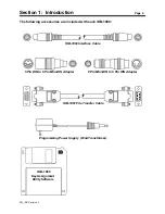
The IKB-1000 communicates with the Computer via a detachable, serial communication cable (model
IKB-1063). One end of the cable should be plugged into the IKB-1000, at the connector labeled "IKB-1000
OUTPUT". This connector is located at the bottom of the rear cover. The other end of the cable should be
connected to the computer's keyboard port. If necessary, use the "6 Pin Mini-DIN to 5 Pin DIN" adapter
provided with the IKB-1000.
The port labeled "AUXILIARY KEYBOARD INPUT", is provided to allow an auxiliary keyboard (perhaps a
standard 101 key keyboard) to communicate with the computer at the same time as the IKB-1000. The "5
Pin DIN to 6 Pin Mini-DIN" adapter is provide for use with external keyboard having 5 Pin DIN connectors.
The IKB-1000 is powered by the computer, through the keyboard cable. The computer supplies 5 VDC
at no more than 275 ma.
The communication signals are low voltage (5 VDC) signals, therefore extra care should be taken when
routing the communication cable. Follow these guidelines for a trouble free installation.
T
Use only shielded cable, and do not use a cable that is more than 10 feet long.
T
Keep the cable away from AC power lines. If possible, keep the cable at least one foot from 120 VAC
lines, and at least two feet away from higher voltage lines.
T
If the cable must cross AC power lines, cross them at right angles.
T
If you route the cable through conduit, the conduit should contain only other low voltage
communication cables or DC signals. Do not run the cable in conduit that contains AC power lines or
RF communication signals.
T
Keep the cable away from sources of high energy fields such as arc welders, AC motors, motor
starters, servo controllers, generators, induction heaters, and transformers.