background image

Section 3:  More about the IKB-1000

Page 10


PM_IKB  Revision 3

3.3  Legend Cards

Each of the 36 user defined keys have a 7/8" square legend area which allows the user to label each key;
a set of legend cards is included. The legend cards are kept clean by inserting them into a 'see through'
pocket underneath the polyester overlay.

To gain access to the pocket in the keyboard overlay, it is necessary to withdraw the keyboard assembly
from the IKB-1000 bezel. To do this, remove the 18, No.6, KEP nuts from the rear of the keyboard backing
plate. The keyboard assembly can now be removed from the bezel.

The three legend card pockets are open at the top edge of the keyboard overlay. After labeling each
legend card, carefully cut it to size and insert it into the pocket from the top down. Assembly of the
keyboard to the bezel is the reverse of removal; take care to align the gasket properly.

3.4  Status LED

The IKB-1000 is provided with a tri-color status LED visible through a hole in the rear cover.

IKB-1000 Status LED Summary

LED Status

Indication

Possible Cause

Steady Green:

Normal keyboard
operation.

Steady Red:

Basic Assurance Test
(BAT) failure.

Bad key assignment file.
Power down then up; if
problem continues,
reprogram the key
assignment file (see
Section 2).

Steady Amber:

The IKB-1000 is in
program mode. It is
waiting for download
from computer.

The IKB-1061 cable is
plugged into the IKB's
programming port.

Green flash:

Key assignment file
successfully
programmed.

Red flash:

Error on key
assignment file
download.

1) Not compatible key
assignment file.

2) Time-out waiting for
computer to download.

Summary of Contents for IKB-1000

Page 1: ...ECH CORPORATION be responsible or liable for any damage including indirect or consequential losses resulting from the use misuse or application of the unit The text illustrations charts and examples i...

Page 2: ...5 2 1 Edit Key Assignment File 6 2 1 1 Macro key sequence 7 2 2 File load and save 7 2 3 Send to IKB 1000 7 2 4 Options 8 2 5 Exit 8 Section 3 More about the IKB 1000 9 3 1 Keys and scan codes 9 3 2 C...

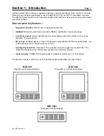
Page 3: ...re ratings Custom key layout 36 user defined keys may be programmed to act like almost any key on the standard 101 key keyboard Macro keys Multiple keystroke macro strings may be programmed into the u...

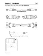
Page 4: ...wing accessories are included with each IKB 1000 IKB 1063 Interface Cable 5 Pin DIN to 6 Pin Mini DIN Adapter 6 Pin Mini DIN to 5 Pin DIN Adapter IKB 1061 File Transfer Cable Programming Power Supply...

Page 5: ...often as needed An auxiliary keyboard port is provided that allows an external keyboard to be active at the same time as the IKB 1000 The IKB 1000 will accept input at the auxiliary keyboard port and...

Page 6: ...the menu use the Arrow keys to highlight Ctrl then press Enter again to make your selection You may program any key or key sequence in the menu using a similar procedure Figure 2 2 Editor s top line...

Page 7: ...000 Also insert the power supply power plug into the socket at the bottom of the rear cover 2 The IKB 1000 has two round DIN connectors located at the bottom of the rear cover one to connect an extern...

Page 8: ...mputers The IKB can be configured as a PC XT type keyboard by selecting XT Key File from the Options menu COM2 By default the IKB 1080 software will use the computer s COM1 port to send the key assign...

Page 9: ...he bottom of the rear cover The other end of the cable should be connected to the computer s keyboard port If necessary use the 6 Pin Mini DIN to 5 Pin DIN adapter provided with the IKB 1000 The port...

Page 10: ...egend card carefully cut it to size and insert it into the pocket from the top down Assembly of the keyboard to the bezel is the reverse of removal take care to align the gasket properly 3 4 Status LE...

Page 11: ...computer to enter Caps Lock mode The computer will stay in Caps Lock mode even if the keyboard is removed until you press the Caps Lock key again The same is true for Num Lock If the computer is in C...

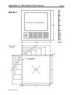
Page 12: ...Appendix A Mechanical Dimensions Page 12 PM_IKB Revision 3 IKB 1011 14 75 Wide x 11 50 High Window All dimensions in inches...

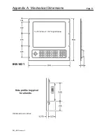
Page 13: ...Appendix A Mechanical Dimensions Page 13 PM_IKB Revision 3 14 75 Wide x 11 50 High Window IKB 1021 Side profile is typical for all units All dimensions in inches...

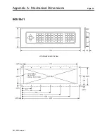
Page 14: ...Appendix A Mechanical Dimensions Page 14 PM_IKB Revision 3 IKB 1041 All dimensions in inches...

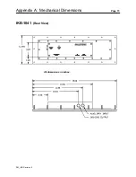
Page 15: ...Appendix A Mechanical Dimensions Page 15 PM_IKB Revision 3 IKB 1041 Rear View All dimensions in inches...

Reviews: