


Section 2: IKB-1000 (User defined keys)
Page 7
PM_IKB Revision 3
the menu, you must select '
Enter
' from the menu to use the [Enter] key in a macro.
The '
Remove
' option acts like a back space key, to delete the last keystroke from the macro string.
The '
Cancel
' option will discard all changes made during the current editing session, and exit the macro
editor.
The '
Done
' option will save any changes made during the current editing session, and exit the macro
editor.
2.2 File
The key assignment file, created using the editor, can be saved to a diskette and, once saved, can be
reloaded into the computer using the 'File' option from the top menu (Figure 2.1). When saving the file to
a diskette, you will be asked to provide a name for the file. The file name must follow MS-DOS file name
conventions, and the whole string, including drive, path, file name, and extension must not exceed 60
characters.
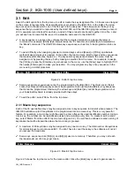
2.3 Send
The 'Send' menu option must be used to send the key assignment file out your computer's serial
communication port, to the IKB-1000. Follow these steps for trouble free operation:
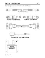
1)
Connect the IKB-1061 File Transfer cable to the serial port located at the left side of the rear
cover on the IKB-1000. Also insert the power supply power plug into the socket at the bottom of
the rear cover.
2)
The IKB-1000 has two round DIN connectors located at the bottom of the rear cover; one to
connect an external keyboard, and one to connect the IKB-1000 to your computer. Remove any
cables that may be connected to the DIN connectors. There should not be any cables connected
to these, while programming the IKB-1000.
3)
The other end of the File Transfer cable (the 9-pin female) should now be plugged into the
computer's serial port (COM1 or COM2).
4)
Apply power to the IKB-1000 by plugging the wall mount transformer into a 120 VAC wall socket.
The LED, next to the serial port, should light amber.
5)
Select 'Send' from the top line menu, to begin the transfer.
The computer will transmit the data file out COM1 or COM2 depending on the serial port switch in the IKB-
1080's option window (see section 2.4). If everything goes well, it will take only a few seconds to transfer
the file. When the file transfer is complete, the status LED on the IKB-1000 will flash green. If the transfer
is not successful, the LED will flash red.
After the key assignment file is successfully programmed, the IKB-1061 cable and power supply must be
removed from the IKB-1000 before normal keyboard operation can begin. If the cable is left in place, the
unit will enter program mode every time power is applied.
2.4 Options


