background image

14 - DC Power Installation and AC-to-DC Power Supply Conversion Guide

6. Turn on the 30-amp circuit breaker between the power-fan canister and the DC power source.
7. Check the green Input DC Power LED and the amber Power Service Action Required LED on the new power-fan

canister.

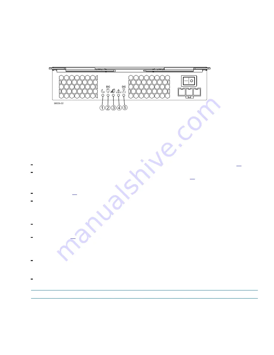
Figure 10. Power-Fan Canister Service Action LEDs

1. Standby Power-Fan LED (Green)
2. Power-Fan DC Power LED (Green)
3. Power-Fan Service Action Allowed LED (Blue)
4. Power-Fan Service Action Required LED (Amber)
5. Power-Fan AC Power LED (Green)

8. Based on the LED status, perform one of these actions:

The Input DC Power LED is on, 

and

 the Power Service Action Required LED is off 

– Go to step 

11

.

The Input DC Power LED is off, 

or

 the Power Service Action Required LED is on

 – Check that the power-

fan canister is installed correctly. Reinstall the power-fan canister. Go to step 

10

.

9. Did this action correct the problem?

Yes 

– Go to step 

11

.

No

 – If the problem has not been resolved, contact your Technical Support Representative.

10.Check the status of all of the trays in the storage array.
11.Does any component have a Needs Attention status?

Yes

 – Click the 

Recovery Guru

 toolbar button in the Array Management Window, and complete the recovery

procedure. If the problem has not been resolved, contact your Technical Support Representative.

No

 – Go to step 

13

.

12.Remove the antistatic protection.
13.Gather support data about your updated storage array by using one of these methods:

Use the storage management software to collect and save a support bundle of your storage array. From the

Array Management Window toolbar, select 

Monitor 

 > 

Health

 > 

Collect Support Data Manually

. Then either

browse or name and specify a location on your system where you want to store the support bundle.
Use the CLI to run the 

save storageArray supportData

 command to gather comprehensive support

data about the storage array.

NOTE  

Gathering support data can temporarily impact performance on your storage array.

For more information about this command, refer to the 

Command Line Interface and Script Commands

Programming Guide

.

Summary of Contents for StorNext QD7000

Page 1: ...DC Power Installation and AC to DC Power Conversion Guide StorNext QD7000 Firmware 8 40 xx xx 6 68674 01 Rev A...

Page 2: ...w and constitutes a punishable violation of the law TRAEMARK STATEMENT Artico Be Certain and the Q brackets design DLT DXi DXi Accent DXi V1000 DXi V2000 DXi V4000 GoVault Lattus NDX the Q logo the Q...

Page 3: ...ecoder section for additional information This section provides the following information Audience Prerequisites NetApp to Quantum Naming Decoder Product Safety Statements Contacts Comments Quantum Gl...

Page 4: ...oduct Nomenclature E Series NetApp Product Quantum Storage Description Controller Drive Tray Base System Quantum uses Base System when referring to a drive tray with the RAID controllers Drive Tray Ex...

Page 5: ...00 E5560 DE6600 4U drive enclosure With E5500 RAID controllers Soyuz Quantum StorNext QD7000 E5460 DE6600 4U drive enclosure With E5400 RAID controllers Pikes Peak Quantum StorNext QD6000 E Series Net...

Page 6: ...ent or interference with other equipment WARNING Before operating this product read all instructions and warnings in this document and in the system safety and regulatory guide E5424 DE5600 24 drive 2...

Page 7: ...Preface vii DC Power Installation and AC to DC Power Conversion Guide...

Page 8: ...orageCare services Service and Support Website Register products license software browse Quantum Learning courses check backup software and operating system support and locate manuals FAQs firmware do...

Page 9: ...assistance or if training is desired contact the Quantum Customer Support Center North America 1 800 284 5101 toll free 1 720 249 5700 EMEA 800 7826 8888 toll free 49 6131 324 185 APAC 800 7826 8887...

Page 10: ...Conversion Guide NetApp Inc 495 East Java Drive Sunnyvale CA 94089 U S Telephone 1 408 822 6000 Fax 1 408 822 4501 Support telephone 1 888 463 8277 Web http www netapp com Feedback doccomments netapp...

Page 11: ......

Page 12: ...C to DC Power Supply Conversion 6 Conversion Kit Contents 6 Preparing to Convert a Tray 6 Removing the AC Power Fan Canisters and Installing the DC Power Fan Canisters 6 Turning on the Power to the Tr...

Page 13: ...ii Table of Contents...

Page 14: ...stall convert or replace a DC power source into an industry standard cabinet This guide is based on the following assumptions The tray you are converting is not installed in a rack and is not in use a...

Page 15: ...te and high quality information If you have suggestions for improving this document send us your comments by email to doccomments netapp com To help us direct your comments to the correct division inc...

Page 16: ...ch power fan canister in the drive tray to maintain power redundancy DC Power Source Precautions WARNING W14 Risk of bodily injury A qualified service person is required to make the DC power connectio...

Page 17: ...ted drive trays until this documentation instructs you to do so NOTE Before turning off any power switches on a DC powered controller drive tray or drive tray you must turn off both two pole 30 amp ci...

Page 18: ...able and Source Wires 1 Supply Negative Brown Wire 48 VDC 2 Return Positive Blue Wire 3 Ground Green and Yellow Wire 4 DC Power Connector 4 Turn on the two pole 30 amp DC circuit breaker for each DC p...

Page 19: ...pes of conversions Conversion Kit Contents The conversion kit contains these items Two DC power fan canisters To convert your tray from an AC power source to a DC power source Two DC power cords Antis...

Page 20: ...er from the chassis b Using the release levers pull the power fan canister from the tray 3 Install the new DC power fan canister a Slowly push the new power fan canister into the empty slot until it s...

Page 21: ...Figure 4 Power Switch on the DC Power Fan Canister 1 Power Switch for the DC Power Fan Canister 4 Wait three minutes for the power up process to complete Checking the Hardware Status The LEDs indicat...

Page 22: ...the problem has not been resolved contact your Technical Support Representative 5 Bring both controllers back online 6 To place controller A back online select Controller A and then select Hardware C...

Page 23: ...ray To correct the problem refer to the documentation for your tray or contact a Technical Support Representative 17 Gather support data about your updated storage array by using one of these methods...

Page 24: ...ction when handling tray components Figure 6 Power Fan Canister and Controller Canister 1 Controller Canister 2 Power Fan Canister To replace a failed power fan canister perform the following procedur...

Page 25: ...er left right is the identifier of the power fan canister you want to replace on the rear of the controller drive tray Valid values are left or right Be sure to type the square brackets around the val...

Page 26: ...an increase in fan speed The fan speed returns to normal after you have replaced the power fan canister Figure 9 Removing a Power Fan Canister 1 Power Fan Canister Latches Installing a New DC Power F...

Page 27: ...n resolved contact your Technical Support Representative 10 Check the status of all of the trays in the storage array 11 Does any component have a Needs Attention status Yes Click the Recovery Guru to...

Page 28: ...cts Statement This equipment uses Small Form factor Pluggable SFP optical transceivers which are unmodified Class 1 laser products pursuant to 21 CFR Subchapter J Section 1040 10 All optical transceiv...

Page 29: ...de potencia incluye el coste de la gesti n de su desecho Translation of Spanish Royal Decree 106 2008 This notice is provided in accordance with the Royal Decree 106 2008 of Spain The retail price of...

Page 30: ...apSuite SnapValidator SnapVault StorageGRID StoreVault the StoreVault logo SyncMirror Tech OnTap The evolution of storage Topio VelocityStak vFiler VFM Virtual File Manager VPolicy WAFL Web Filer and...

Page 31: ...REMENT OF SUBSTITUTE GOODS OR SERVICES LOSS OF USE DATA OR PROFITS OR BUSINESS INTERRUPTION HOWEVER CAUSED AND ON ANY THEORY OF LIABILITY WHETHER IN CONTRACT STRICT LIABILITY OR TORT INCLUDING NEGLIGE...

Page 32: ......

Page 33: ......

Reviews: