background image

Procedure

Quantum Smart-1 6000-L/6000-XL Appliances Replacing SAN Cards    |   9

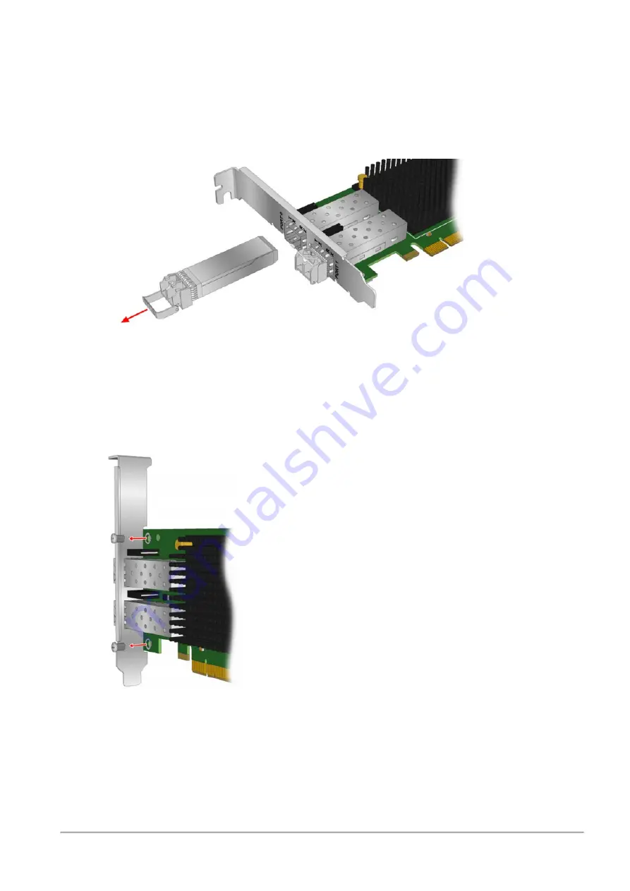
To remove the transceivers:

1. Pull the bail (handle) out and down to release the latch for a typical optical transceiver.

2. Pull the transceiver gently (without force).

3. The transceiver slides out easily after the latch releases.

4. Remove the second optical transceiver.

5. Store the transceivers in a safe place using ESD (Electrostatic Discharge) precautions such as

antistatic bags.

To remove the bracket:

1. Remove the mounting bracket screws from the top of the adapter.

2. Remove the bracket.

Summary of Contents for SMART-1 6000-L

Page 1: ...Classification Protected 17 February 2022 QUANTUM SMART 1 6000 L 6000 XL APPLIANCES REPLACING SAN CARDS...

Page 2: ...y precaution has been taken in the preparation of this book Check Point assumes no responsibility for errors or omissions This publication and features described herein are subject to change without n...

Page 3: ...s For third party independent certification of Check Point products see the Check Point Certifications page Check Point Quantum Smart 1 6000 L 6000 XL Appliances Replacing SAN Cards For more about thi...

Page 4: ...ents 6 Procedure 7 Preparing the Appliance 7 Replacing the Bracket on a SAN Card 8 Removing the Riser 10 Installing an Expansion SAN Card into the Riser 11 Removing an Expansion SAN Card from the Rise...

Page 5: ...n or as directed by the technical support n We recommend that you always use an antistatic mat and antistatic strap on your wrist while working on components inside the appliance n To ensure proper op...

Page 6: ...Hardware Components Quantum Smart 1 6000 L 6000 XL Appliances Replacing SAN Cards 6 Hardware Components Item Description 1 Front panel 2 Riser 1 3 Rear panel...

Page 7: ...ance 5 Install a transceiver To replace an existing expansion SAN card 1 Prepare the appliance with a shut down halt and disconnection of power 2 Remove the existing expansion SAN card from the riser...

Page 8: ...to rotate the latch release lock counter clockwise to the unlocked position b Lift the latch c Slide the cover back The tabs on the cover should disengage from the guide slots on the appliance d Hold...

Page 9: ...l transceiver 2 Pull the transceiver gently without force 3 The transceiver slides out easily after the latch releases 4 Remove the second optical transceiver 5 Store the transceivers in a safe place...

Page 10: ...Form Factor Pluggable transceiver cages n Make sure that the LEDs for the SAN card ports align properly with the holes in the bracket 4 Reinstall the screws to attach the new bracket to the SAN card T...

Page 11: ...d latch and remove the filler bracket 3 Hold the card by its edges and align the card edge connector with the expansion SAN card connector on the riser 4 Insert the card edge connector firmly into the...

Page 12: ...es out of the slot 2 Hold the expansion SAN card by its edges and pull the card until the card edge connector disengages from the expansion SAN card connector on the riser Note If you do not immediate...

Page 13: ...the cover with the guide slots on the appliance c Push the latch down d Slide the cover forward The tabs on the cover should engage with the guide slots on the appliance The latch should lock into pl...

Page 14: ...transceivers Note The optical transceivers on the SAN card are delicate n Remove and install the transceivers carefully n Use ESD Electrostatic Discharge precautions such as an antistatic floor mat an...

Page 15: ...Maximum Length Min Length Connector OM4 Multimode 50 125 micron fiber 4700 MHz km bandwidth cable 4GFC 0 5m to 400m 8GFC 0 5m to 190m 16GFC 0 5m to 125m 0 5m LC OM3 Multimode 50 125 micron fiber 2000...

Page 16: ...f Off No SFP modules installed or boot failure dead board Off On POST failure dead board Off Slow blink Boot failure after POST Off Flashing POST processing in progress On Off Failure in common code m...

Reviews: