Quantum ELM Replacement Instructions Manual Download Page 10

ELM & ELM2 EMERGENCY LIGHTING UNIT RECALL INSPECTION & CIRCUIT BOARD REPLACEMENT INSTRUCTIONS | 10

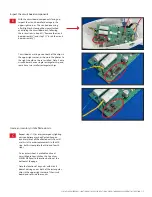
The unit should be affixed to its mounting plate 

with the snaps aligned, as shown in the photo 

to the right. Align the holes on the bottom of the 

housing with the circular snaps at the bottom 

of the mounting plate, and push the housing 

directly onto the mounting plate. The two snaps 

at the bottom, as well as the two hidden snaps 

at the top, should make an audible snap when 

fully engaged. Note: Do NOT attempt to mount 

the light unit to its mounting plate at an angle. 

Ensure that the unit is mounted squarely to the 

wall, without leaning, rocking or any gaps.

Attach the unit to the mounting plate:

B

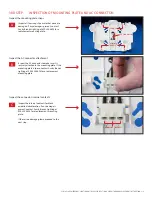
Apply continuous power to the unit. The test 

switch/indicator light should illuminate red.

Caution: Battery must be connected to 

the light unit prior to applying AC power. 

Damage to the battery will occur if the 

battery is connected for a prolonged 

period of time (24 hours or longer) without 

continuous AC power being provided. 

Allow the battery to charge for 48 hours for 

full charge.

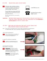
After full battery recharge, press the test 

switch. Both lampheads should illuminate. 

If one or more lamps do not illuminate, 

contact Acuity Brands Lighting at 

800.334.8694 to discuss an appropriate 

solution.

If your light unit is an ELM2 model, aim 

lampheads to the desired position.

D

E

F

G

Bottom

Top

T

est Switch/ 

Indicator Light

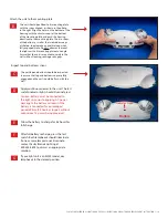
Inspect top and bottoms snaps:

C

The unit top and bottom should be inspected 

to ensure that top and bottom snaps are fully 

engaged and the unit should be flush with the 

wall.

Summary of Contents for ELM

Page 1: ...ing light unit models ELM2 SD ELM2 LED ELM2 WRS Check the label inside your unit to verify the model number Call Acuity Brands Lighting with any questions 888 615 4501 The two circuit board revisions...

Page 2: ...e circuit boards that are beige on one or both sides like the one depicted below are NOT part of the recall Press both circular snaps at the bottom of the housing Rotate the housing upward and pull i...

Page 3: ...re installed Note Some circuit boards have a single rectangular chip and some have two smaller rectangular chips Inspect the circuit board components B Repeat steps 1 2 for every emergency lighting u...

Page 4: ...mounting plate is loose contact Acuity Brands Lighting at 800 334 8694 for a replacement mounting plate Inspect the internal contacts for black oxidation discoloration If any damage is present contac...

Page 5: ...inuous AC power being provided Allow the battery to charge for 48 hours for full charge After full battery recharge press the test switch Both lampheads should illuminate If one or more lamps do not i...

Page 6: ...SAFEGUARDS ON FRONT COVER SHEET 6TH STEP REMOVING AND REPLACING RECALLED CIRCUIT BOARD ONCE REPLACEMENT BOARD HAS BEEN RECEIVED Remove the affected emergency lighting units from the wall Refer to you...

Page 7: ...which will be disconnected in the next step BOTH ELM ELM2 units Disconnect the blue battery connector at the circuit board located at the BLUE BATT terminal Use needle nosed pliers to unplug the batt...

Page 8: ...s will be discarded with only the red wire attached Destroy and discard recalled circuit board F 7TH STEP INSTALLING THE NEW CIRCUIT BOARD Use needle nosed pliers to connect the blue wire terminal by...

Page 9: ...edge connectors will point toward the open back of the fixture The snaps should click when the circuit board is fully seated The board as properly installed is shown in the photo in the 8th step Inser...

Page 10: ...e B Apply continuous power to the unit The test switch indicator light should illuminate red Caution Battery must be connected to the light unit prior to applying AC power Damage to the battery will o...

Page 11: ...ELM ELM2 EMERGENCY LIGHTING UNIT RECALL INSPECTION CIRCUIT BOARD REPLACEMENT INSTRUCTIONS 11 Wiring Diagram for reference Part EMCSA00852 rev A...

Reviews: