T
ROUBLESHOOTING
S
ERVER
B
OOT
I
SSUE
T
OPICS
7-4
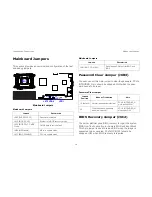
If you cannot access the BIOS Setup Utility, clear the CMOS by
performing the following steps:
1. Power down the server. Do not unplug the power cord.
2. Open the server chassis
3. Move the CMOS CLEAR jumper from the default opera-
tion position, covering pins 1 and 2, to the reset / clear
CMOS, covering pins 2 and 3.
4. Remove AC power.
5. Wait 5 seconds.
6. Move the jumper back to default position, covering pins 1
and 2.
7. Close the server chassis and power up the server.
The CMOS is now cleared and can be reset by going into BIOS
setup.
Please refer to
http://www.QuantaQCT.com
for the BIOS
update.
Installation Problems
Perform the following checks if you are troubleshooting an
installation problem:
Check all cable and power connections (including all rack cable
connections). Unplug the power cord, and wait one minute.
Then reconnect the power cord and try again. If the network is
reporting an error, see if the server has enough memory and
disk space available. Remove all added options, one at a time,
and try to power up the system. If after removing an option the
server works, you may find that it is a problem with the option or
a configuration problem between the option and the server.
Contact the option vendor for assistance.
If the system doesn't power on, check the LED display. If
the power LED is not on, you may not be receiving AC
power. Check the AC power cord to make sure that it is
securely connected.
Troubleshooting External Connections
Loose or improperly connected cables are the most likely
source of problems for the system, monitor, and other peripher-
als (such as a keyboard, mouse, or other external device).
Ensure that all external cables are securely attached to the
external connectors on your system.
Summary of Contents for STRATOS S210 Series S210-X2A2J
Page 21: ...SAFETY INFORMATION XXI ...
Page 23: ...About the Server Chapter 1 ...
Page 33: ...Installing Hardware Chapter 2 ...
Page 106: ...BIOS Chapter 3 ...
Page 166: ...BMC Chapter 4 ...
Page 229: ...Jumpers and Connectors Chapter 5 ...
Page 236: ...Rail Kit Assembly Chapter 6 ...
Page 240: ...Troubleshooting Chapter 7 ...
Page 245: ...Installation and Assembly Safety Instructions Chapter 8 ...
Page 249: ...Safety Information Chapter 9 ...
Page 258: ...Regulatory and Compliance Infor mation Chapter 10 ...


