background image

1. Introduction 


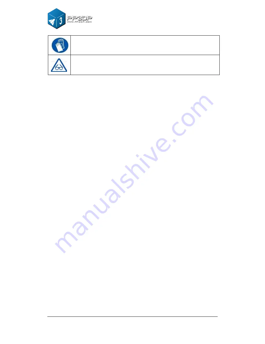
Gloves:  When  performing  a  certain  maintenance  work,  machine 
may be hot and protective gloves are required to avoid being burnt. 


Safety Glasses: Wear safety glasses to avoid injury to the eyes. 


1.2.2 Protection 

  Q150  printer  must  not be  exposed  to  water or  rain,  otherwise  may  cause 

damage. 

  Do not shut down Q150 Printer or pull the USB cable during the process of 

loading  a  digital  model  to  Printer,  otherwise  the  model  data may  not  be 
transmitted successfully. 

  When using the “Extrude” function, keep at least 50mm gap between the 

nozzle  and  the  print  platform.  If  the  gap  is  too  small,  nozzle  may  not 
extrude filament easily, which could cause nozzle clog. 

  Q150 printer is designed to function properly at temperature between 15°C  

and 30°C  and humidity between 20% and 50%; Operating outside these 
limits may cause low print quality.

Summary of Contents for Q150

Page 1: ...www com ly ita k o USER MANUAL 150...

Page 2: ...3 2 1 Start the program 16 3 2 2 Loading a 3D model 16 3 2 3View Options 19 3 2 4 Model transformations 20 3 2 5 Placing models onto the build platform 22 3 3 GETTING READY TO PRINT 23 3 3 1 Initializ...

Page 3: ...nozzle and printed model are still hot In order to avoid being burnt or cause deformation of model do not touch model nozzle or print platform by hand without any protection Protective glasses should...

Page 4: ...Q150 Printer or pull the USB cable during the process of loading a digital model to Printer otherwise the model data may not be transmitted successfully When using the Extrude function keep at least 5...

Page 5: ...The machine and software allow you to print great models with only a few keystrokes even you are a first time user of Q150 printer Q150 uses a nozzle to deposit molten plastic and the printed parts a...

Page 6: ...2 Overview 6 Figure 2 2 Inside View Figure 2 3 Back view Platform Extrusion head Nozzle USB Interface Power Interface Roller Shaft Power On off...

Page 7: ...erview 7 USB cable Power adapter 20 V Filament tube Screws Cell board Extrusion head ABS spool Figure 2 4 Accessories Pen Knives Tweezers Hex wrench Shovel Pliers Gloves Nozzle wrench Figure 2 5 Tool...

Page 8: ...aterial Color White Black Red Yellow Blue Green Layer Thickness 0 2 0 35 mm Print Speed 10 100 cm3 h Print Size 120 120 120 mm Printer Weight 5 KG 11 lb Printer Size 240 350 350 mm 2 2 2 Other Specifi...

Page 9: ...2 Overview 9 Input Format STL OS compatibility Windows XP Vista 7 8 Mac 2 2 3 Environmental specifications Ambient Temperature 15 C 30 C Relative humidity 20 50...

Page 10: ...allation Figure 3 1 Print head installation Extrusion Head The extrusion head of a Q150 is fastened by three magnetic buckles When assembling extrusion head make sure the extrusion head is securely co...

Page 11: ...cell board into the platform slot Moderate force is recommended when inserting the cellboard Figure 3 3 Roller Shaft Roller shaft Insert the roller shaft into the hole at the back of printer and pres...

Page 12: ...tware installation procedure in section 3 1 2 connect the computer with printer through USB cable initialize the printer from the software and in the software menu click 3D Print Maintenance to bring...

Page 13: ...e 3 5 Maintenance Dialog 3 1 2 Software Installation The software is available for download on our site quant3D com It is free for everyone who owns a Quant3D printer After downloading the software in...

Page 14: ...1 3 Driver Installation Connect the printer to a computer with a USB cable The computer should pop up the Found New Hardware Wizard window Choose No not this time option and then click Next Choose Ins...

Page 15: ...tion The following dialogue box pops up Choose Continue Anyway and the drivers will install automatically Figure 3 9 Snap shots of Software installation If you have any problems installing the driver...

Page 16: ...artup Screen 3 2 2 Loading a 3D model Click File Open or on the toolbar and select the model you want to load UP software supports STL files the standard input format for 3D printing and the UP3 forma...

Page 17: ...ou want to add See the Placing models on the build platform section for more information Unloading a model click the left mouse button on the model to select it and then click Unload on the toolbar or...

Page 18: ...and if the model is picked or highlighted its color is pink If the model has problems like the normal of triangles of a model is facing a wrong direction the model will be colored in red All the setti...

Page 19: ...se and keyboard combinations Rotate Press the mid button of mouse and hold and move the mouse You can rotate the view and observe the model from different angles Pan Press Ctrl key and hold press mid...

Page 20: ...ving a model Click the Move button and in the text box choose or input the distance you want to move the model then choose the axis direction along which you want to move the model by clicking the axi...

Page 21: ...the toolbar in the text box choose or input the value of rotating degree you want to rotate the model then choose the axis along which the model rotates by clicking the axis button For example Rotate...

Page 22: ...long the Z axis only Procedures 1 Click Scale 2 Input 1 2 in the text box 3 Click Z axis Figure 3 18 Scale a model Unit Conversion This option is provided as a convenient tool to convert models betwee...

Page 23: ...on on the toolbar choose or input the distance in the text box and then choose the axis for the direction along which you want to move the model NOTE When more than one model is loaded the gap between...

Page 24: ...in the 3D Print menu 3 3 2 Preparing Platform Before printing print platform must be prepared so that the model can adhere to the platform and does not move during the printing process The cell board...

Page 25: ...ction of the entire manual Please read it carefully and make sure that you understand the nozzle height setup procedure which is vital to successful 3D printing In order to print successfully the plat...

Page 26: ...from platform to nozzle is 135 9mm after the printer is initialized and before the printing starts To figure out the correct nozzle height please follow the following steps 1 Open the Maintain dialog...

Page 27: ...for example the platform appears to be far away say 7mm from the nozzle increase the number in the text box to 130 and click the To button After the platform finished upward movement we can enter a bi...

Page 28: ...ece of paper the thickness of a paper is about 0 1mm and put it between the nozzle and platform NOTE The maximum height of print platform will be set 1mm higher than the value set in the text box For...

Page 29: ...Maintain on the 3D Print menu and the following dialog box pops up Windows version Mac version Figure 3 25 Maintenance Dialog Extrude Extrudes material out of print nozzle Click on this button and th...

Page 30: ...nd warn you if you don t have enough material left to print your model before the printing starts Click this button and enter the value of how many grams of material you have on the current spool If i...

Page 31: ...some objects into the inside of the model and then resume the unfinished print job Nozzle Platform The five buttons FL FR Center NL and NR control the position of nozzle and platform Nozzle moves to...

Page 32: ...support layer is printed under the part When the printer starts printing it first prints a raft of non solid material in which all the lines of support material are horizontal along the Y axis It buil...

Page 33: ...d dense support is determined by the Dense parameter under the Support options as described below Figure 3 27 Support structure on different portion of parts Fill Options There are four modes for infi...

Page 34: ...ort structure generated by different infill options Shell Mode This mode prints model with no infill structure which helps improve efficiency by printing hollow model If you simply want to print model...

Page 35: ...3 Operation 35 Please check the following pictures for the differences of the two printing modes Figure 3 28 Shell mode and Surface mode...

Page 36: ...is a number of layers of structure and the default number of layers is 3 The option here is to allow user to set the value from 2 to 6 Basically the bigger the gap between infill the bigger the numbe...

Page 37: ...tion of a part on print platform is also critical when considering how much support material gets used and how difficult support structure can be removed As a general rule it is easier to remove suppo...

Page 38: ...and faster print speed is achieved Figure 3 32 Support Structure for Small Area Other Options Stable Support Stable support creates more solid support The model printed with this option is less likel...

Page 39: ...computer via USB cable initialize the printer prepare the cell board and insert it to the platform Load the model and place it properly in the software Check if there is enough material for the model...

Page 40: ...y short time so that the surfaces in these models can have better quality Regular models if printed with door open could have warping or cracking in the printed parts Click menu 3D Print Print and the...

Page 41: ...option No Raft Raft is the base for models printing over cell board Setting this option allows printing without base This option is mainly used with other platform board and printing with this option...

Page 42: ...e based on the ABS material sold on quant3d com The easiest way to calculate how much material one print is about to consume is to use the Print Preview option under the 3D Print menu The software wil...

Page 43: ...wly wiggle it back and forth to pry loose the model Remember to wear gloves during the whole time of printing because the board and the model maybe still hot TIP It is highly recommended to avoid remo...

Page 44: ...easy to remove the support structure from the model Figure 5 1 shows an example print a teapot The left picture shows the teapot model with support structure removed and the right picture shows the te...

Page 45: ...rt structure but it can become quite satisfying as you discover the shapes of your new creation CAUTION ALWAYS WEAR SAFETY GLASSES WHEN REMOVING SUPPORT STRUCTURE ESPECIALLY WHEN WORKING WITH PLA MATE...

Page 46: ...5 Model Removal 46...

Page 47: ...ntil the material is about 10cm out of the other end of the tube then insert it into the hole at the top of the extrusion head installed on the machine Extrude the new material Select maintain from th...

Page 48: ...axes First the Software provides a calibration model located in the directory Example Print the calibration model on your printer Figure 6 1 Calibration Model After the calibration model is printed me...

Page 49: ...er L shaped component on the front and measure its Z deviation as shown in Figure 6 3 Put the exact value into the Z box If it deviates to the right the value put into the Z box should be a positive v...

Page 50: ...to be cleaned regularly Firstly in order to melt the oxidized ABS nozzle needs to be heated Use the Extrude button in the Maintain dialogue then lower the platform to the bottom Then use some heat res...

Page 51: ...it is much easier to remove the nozzle when it is hot If you need more force than the nozzle wrench can provide use it with a small Allen Key provided in the tool kit Figure 6 6 Changing Nozzle 6 6 M...

Page 52: ...ential to minimize the warping Also the faster you can print such parts the less lifting you are likely to get Here are some other tips to increase print quality If possible try to avoid printing such...

Page 53: ...en bearing and filament feed rollers is too wide Cannot communicate with printer 1 Make sure printer is connected to a computer via a USB cable 2 Unplug the USB cable then plug it in again 3 Reset the...

Page 54: ...Click Device Manager button and Device Manager Dialog pops up Find the entry 3DPrinter FreeMC in the USB section Figure 8 2 Device Manager Dialog 3 Click the right mouse button and select the Uninsta...

Page 55: ...e USB cable then plug it in again Windows will find a new device Manually select driver folder Default is C Program files UP Driver or C Program files X86 UP Driver if Windows is a 64bit system 6 A ne...

Page 56: ...lly 1 Install the latest software version 2 Find the 3DPrint FreeMC driver in the Device Manager dialog box it should be located in the USB section Figure 8 5 Device Manager Dialog 3 Select Update Dri...

Page 57: ...Select the UP driver folder the default is C program files UP Driver Figure 8 7 Select Driver Directory 5 A Free Motion Card section should now have been created in Device Manager Figure 8 8 Free Mot...

Page 58: ...www ly ita k o com version Q1501...

Reviews: