Page 2
7037-135E
September 1, 2008
R
4300 Wood Stove Series (ACC)
Hearth & Home Technologies welcomes you to our tradi
-
tion of excellence! In choosing a Quadra-Fire appliance,
you have our assurance of commitment to quality, durabil
-
ity, and performance.
This commitment begins with our research of the market,
including ‘Voice of the Customer’ contacts, ensuring we
make products that will satisfy your needs. Our Research
and Development facility then employs the world’s most
advanced technology to achieve the optimum operation of
our stoves, inserts and fireplaces. And yet we are old-fash
-
ioned when it comes to craftsmanship. Each unit is meticu
-
lously fabricated and surfaces are hand-finished for lasting
beauty and enjoyment. Our pledge to quality is completed
as each model undergoes a quality control inspection.
We wish you and your family many years of enjoyment in
the warmth and comfort of your hearth appliance. Thank
you for choosing Quadra-Fire.
and Welcome to the Quadra-Fire Family
!
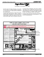
Serial No.
Model Name
Test Lab &
Report No.
Mfg. Date
SAMPLE OF SERIAL NUMBER / SAFETY LABEL
LOCATION: BACK OF APPLIANCE
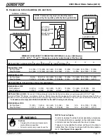
INSTALLATION: FULL VERTICAL OR HORIZONTAL WITH MINIMUM 2 FOOT VERTICAL OFF STOVE TOP
INSTALLATION: ENTIÈREMENT VERTICALE OU HORIZONTALE AVEC 609mm VERTICAL MINIMUM DU HAUT DU POÊLE
SINGLE WALL PIPE
A
B
C
D
E
F
G
H
Flat Top Model
18 (457) 15.5 (394) 26 (660) 17 (432) 10 (255) 18.5 (470) 52.5 (1334) 18 (457)*
Step Top Model
12 (305) 8.5 (216) 23 (584) 13 (330) 2 (51) 13 (330)
50.5 (1283) 18 (457)*
DOUBLE WALL PIPE
Flat Top Model
13 (330) 10.5 (267) 24.5 (622) 15 (381) 10 (255) 18.5 (470) 52.5 (1334) 10 (254)
Step Top Model
10 (254) 6.5 (165) 23 (584) 13 (330) 2 (51) 13 (330)
50.5 (1283) 5 (127)
INSTALLATION: 90o ELBOW OFF TOP OF STOVE THROUGH BACKWALL
INSTALLATION: 90o DU COURBURE AU DESSUS DE HAUT DU POÊLE A TRAVERS LE MUR ARRIÈRE
DOUBLE WALL PIPE
Flat Top Model
8.5 (216) 6 (152) 24.5 (622) 15 (381) 10 (254) 18.5 (470) 52.5 (1334) 18 (457)*
Step Top Model
7.5 (191) 4 (102) 19 (483) 9 (229) 2 (51) 13 (330)
50.5 (1283) 18 (457)*
I
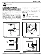
NSTALLATION: ALCOVE -
Six inch (6 inches) (152mm) diameter listed DOUBLE WALL air insulated connector pipe with UL103 HT* listed factory-built Class "A" chimney, or a masonry chimney. (Mobile Home
must be equipped with a spark arrestor.) Maximum depth of Alcove shall be no more than 48 inches (1220mm) with a minimum height of 45.5 inches (1156mm) to top of unit, and the referenced clearances. Please
refer to the clearances below for minimum Alcove height requirement to top of unit.
INSTALLATION: ALCÔVE - De six (6 inches) (152mm) de diamètre, le connecteur du conduit d'air isolé pour mur double avec une cheminée bâtit en usine UL103HT de Classe "A", ou une cheminée de briques. (Les maisons
mobiles doivent être équipées d'un arrêt d'étincelle). La profondeur maximum de l'alcôve ne doit pas être de plus de 48 inches (1220mm) avec une hauteur minimum de 45.5 inches (1156mm) du haut de l'appareil, et des espaces
libres alloués. Référez vous s'il vous plaît aux dégagements repirs ci-dessus pour la hauteru minimum requise entre le dessus ole l'appareil et l'alcove (de la chimineé).
DOUBLE WALL PIPE
Flat Top Model
13 (330) 10.5 (267) 24.5 (622) 15 (381)
N/A
N/A
52.5 (1334)
N/A
Step Top Model
10 (254) 6.5 (165) 23 (584) 13 (330)
N/A
N/A
37 (940)
N/A
*In Canada must comply with Standard CAN/ULC-S629-M87 for the 650oC Factory-built chimney.
*Au Canada doit conformer a CAN/ULC-S629-M87 la norme pour 650oC cheminée bâtit en usine.
*
NFPA 211 MINIMUM CLEARANCES - NOT TESTED
SPÉCIFICATIONS DE LA VENTILATION:
MUR SIMPLE: De six (6 inches) (152mm) de diamètre le connecteur de conduit de minimum
d'acier noir ou bleu de minimum de 24MSG, avec une cheminée bâtit en usine UL103HT* de
Classe "A", adéquate pour usage avec les combustions solides, ou une cheminée de briques,
avec espaces libres référés.
MUR DOUBLE: De six (6 inches) (152mm) de diamètre, le connecteur du conduit d'air isolé
pour mur double avec une cheminée bâtit en usine UL103HT* de Classe "A:, ou une cheminée
de briques, avec espaces libres alloués.
MAISON MOBILE: Utiliser un conduit de mur double par Dura-Vent DVL, Selkirk Metalbestos
DS ou Security DL. Doit être équipé d'un arrêt d'étincelle. Utiliser les espaces libres pour mur
double comme mentionné ci-bas.
MINIMUM CLEARANCES TO COMBUSTIBLE MATERIALS: In Inches & (Millimeters)
NOTE: All "A" , "C" and "F" Dimensions are to inside diameter of the flue collar.
LISTED ROOM HEATER, SOLID FUEL TYPE.
ALSO FOR USE IN MOBILE HOMES. (UM) 84 HUD
1445 N. Highway, Colville, WA 99114
www.quadrafire.com
I
n
stall and use only in accordance with
manufacturer's installation and operating
instructions. Contact local building or fire
officials about restrictions and installation
inspections in your area. Do not obstruct the
space beneath heater.
WARNING - For Mobile Homes: Do not install
in a sleeping room. An outside combustion air
inlet must be provided and unrestricted while unit
is in use. The structural integrity of the mobile
home floor, ceiling and walls must be maintained.
The stove needs to be properly grounded to the
frame of the mobile home. Components required
for mobile home installation: Outside Air Kit, Part
Number OAK-ACC.
Refer to manufacturer's instructions and
local codes for precautions required for passing
chimney through a combustible wall or ceiling
and maximum offsets.
Inspect and clean chimney frequently - Under
Certain Conditions of Use, Creosote Buildup May
Occur Rapidly.
Do not connect this unit to a chimney serving another
appliance.
Optional Components: Optional Blower, Part
BK-ACC.
Electrical Rating: 115 VAC, 1.2 Amps, 60 Hz.
Route power cord away from unit. Do not route
cord under or in front of appliance.
DANGER: Risk of electrical shock.
Disconnect power supply before servicing.
Replace glass only with 5mm ceramic available
from your dealer.
Do not use grate or elevate fire. Build wood fire
directly on hearth.
Do not overfire - if heater or chimney
connector glows, you are overfiring.
Operate only with the fuel loading door
closed. Open only to add fuel to the fire.
CAUTION
:
U.S. ENVIRONMENTAL PROTECTION AGENCY - Certified to
comply with July 1990 particulate emission standards.
2008 2009 2010 Jan. Feb. Mar. Apr. May June July Aug. Sept. Oct. Nov. Dec.
PREVENT HOUSE FIRES
FLOOR PROTECTION
:
Floor protector must be a 3/8 inch min. thickness,
non-combustible material or equivalent, extending
beneath heater and to front/sides/rear as indicated on
the diagram below. Exception: Non-combustible floor
protections must extend beneath the flue pipe when
installed with horizontal venting and extend 2 inches
(51mm) beyond each side.
O-T L
Tested and
Listed by
Portland
Oregon USA
OMNI-Test Laboratories, Inc.
C
Report / Rapport
#061-S-67-7
TESTED TO:/ TESTÉ À:
UL 1482, ULC S627-00
HOT WHILE IN OPERATION DO NOT TOUCH, KEEP CHILDREN AND CLOTHING AWAY. CONTACT MAY CAUSE SKIN BURNS. KEEP FURNISHINGS AND OTHER
COMBUSTIBLE MATERIAL FAR AWAY FROM THE APPLIANCE. SEE NAMEPLATE AND INSTRUCTIONS.
VENT SPECIFICATIONS:
SINGLE WALL: Six inch (6 inches) (152mm) diameter, minimum 24 MSG black or blued steel connector
pipe, with a listed factory-built UL103HT* Class "A" chimney, suitable for use with solid fuels, or a
masonry chimney, and the referenced clearances.
DOUBLE WALL: Six inch (6 inches) (152mm) diameter, listed double wall air insulated connector pipe
with listed factory-built UL103HT* Class "A" chimney, or a masonry chimney and the referenced
clearances
MOBILE HOME: Use double wall pipe by Dura-Vent DVL, Selkirk Metalbestos DS or Security DL double
wall connector pipe. Must be equipped with a spark arrestor. Apply double wall clearances below when
installing unit.
SERIAL NO.
/
NUMÉRO D
E
SÉRIE
4300 ACC Series
R
7037-136
CHAUD LORS DE L'OPÉRATION. NE PAS TOUCHER. GARDEZ LES ENFANTS ET LES VÊTEMENTS LOIN DE L'ESPACE DÉSIGNÉ DE L'INSTALLATION. LE CONTACT PEUT CAUSER DES
BRÛLURES À LA PEAU. GARDEZ LES MEUBLES ET LES MATÉRIAUX COMBUSTIBLES LOIN DE L'ESPACE DÉSIGNÉ DE L'APPAREIL. VOIR L'ÉTIQUETTE ET LES INSTRUCTIONS.
ATTENTION:
APPAREIL DE CHAUFFAGE DE PIÈCE, DE TYPE DE
COMBUSTIBLE SOLIDE, POUR USAGE DANS LES
MAISONS MOBILES. (UM) 84 HUD.
"Pour Usage
Avec Bois Solide Seulement"
I
nstallez et utilisez en accord avec les instructions
d'installation et d'opération du fabricant. Contactez le
bureau de la construction ou le bureau des incendies au
sujet des restrictions et des inspections d'installation dans
votre voisinage. Ne pas obstruez l'espace en dessous de
l'appareil.
AVIS - Pour Les Maisons Mobiles: Ne pas installer dans
une chambre à coucher. Un tuyau extérieur de combustion
d'air doit être installé et ne doit pas être obstrué lorsque
l'appareil est en usage. La structure intégrale du plancher,
du plafond et des murs de la maison mobile doit être
maintenue intacte. L'appareil de chauffage doit être fixé à
la charpente de la maison mobile. Les composants requis
pour l'installation des maisons mobiles: Assemblage d'air
extérieur, Numéro de Pièce OAK-ACC..
Référez vous aux instructions du fabricant et des codes
locaux pour les précautions requises pour passer une
cheminée à travers un mur ou un plafond combustibles, et les
compensations maximums.
Inspectez et nettoyez la cheminée fréquemment. Sous
certaines conditions, il se peut que la créosote s'accumule
rapidement.
Ne pas connecter cet appareil à une cheminée servant un
autre appareil.
Composants Optionnels: Ventilateur Optionnel, Pièce
BK-ACC.
Puissance Électrique: 115 VAC, 1.2 Amps, 60 Hz.
Éloignez le fil électrique de l'appareil. Ne pas faire passer
le fil électrique au dessus ou en dessous de l'appareil.
DANGER: Il y a risque de décharge électrique.
Déconnectez le fil électrique de la prise de contact avant le
service.
Remplacez la vitre seulement avec une vitre céramique de
5 mm disponible chez votre fournisseur.
N'élevez pas le feu. Bâtissez le feu de bois directement sur
l'âtre.
Ne pas surchauffer. Si l'appareil de chauffage ou le tuyau
de cheminée rougissent, vous surchauffez.
Opérez l'appareil seulement lorsque la porte de
chargement est fermée. Ouvrez la porte seulement lorsque
vous devez ajouter des combustibles dans le feu.
PRÉVENTION DES FEUX DE MAISON
PROTECTION DU PLANCHER:
Le protecteur de plancher doit être d'un minimum de 3/8
inch d'épaisseur, de matériel incombustible ou équivalent,
s'étendant du dessous de l'appareil de chauffage à
l'avant, aux cotés et à l'arrière comme indiqué sur le
diagramme suivant. Exception: Les protections
incombustibles du plancher doivent s'étendre en dessous
du conduit de cheminée lorsqu'installées avec une
ventilation à l'horizontale et s'étendre de 2 inches (51mm)
de chaque côté.
ESPACES LIBRES MINIMUM DES MATÉRIAUX COMBUSTIBLES:En Pouces & (millimètres)
NOTE: Toutes les dimensions "A", "C", et "F" sont à partir du diamètre intérieur de l'entrée du conduit.
BACKWALL/SIDEWALL
MUR ARRIÈRE/MUR DE CÔTÉ
CORNER INSTALLATION
/
INSTALLATION DU COIN
ALCOVE TOP VIEW /
VUE DU HAUT DE L'ALCÔVE
ALCOVE SIDE VIEW /
VUE DE CÔTÉ DE L'ALCÔVE
DO NOT REMOVE THIS LABEL / NE PAS ENLEVER L'ÉTIQUETTE
Made in U.S.A./Fait Aux États-Unis
Manufactured by:
Fabriqué par:
G
A
B
C
D
A
B
C
D
90
o
OFF TOP
UP & OUT CEILING CLEARANCE
ESPACE LIBRE DU DESSUS DE
L'APPAREIL AU PLAFOND AVEC 90
DE COURBURE
STOVE TO CEILING CLEARANCE
ESPACE LIBRE DU POÊLE AU
PLAFOND
G
G
H*
E
F
E
F
G
H
G
A
B
16" from glass
8"
USA
Fuel loading door
4-1/2"
3-1/2"
31-5/8" minimum
40-7/16"
minimum
CANADA
203mm (8")
203mm
(8")
203mm
(8")
457mm (18")
1281mm
(50-7/16")
minimum
1080mm (42-1/2")
minimum
CONDUIT DU MUR SIMPLE
Modèle au dessus en appartement
Modèle au dessus en escalier
CONDUIT DU MUR DOUBLE
Modèle au dessus en appartement
Modèle au dessus en escalier
CONDUIT DU MUR DOUBLE
Modèle au dessus en appartement
Modèle au dessus en escalier
CONDUIT DU MUR DOUBLE
Modèle au dessus en escalier
Modèle au dessus en appartement
007003
SAMPLE


