background image

Grand Bay 40 Gas Freestanding  

Page 24

January 2000

January 2000

FI

RS

T                F

IR

E

FIRST FIRE

NOTE:  

Never operate this appliance with the door open.

NOTE:

  No electrical power supply is required for the gas control to operate.  Standing pilot

                 allows the valve to operate with manual switch or millivolt thermostat.

WARNING:   When  the  appliance  is  equipped  with  a  24  karat  gold-plated  door, 

you must clean all the fingerprints and oils from the gold surface before firing the 

appliance for the first time.  Use a glass cleaner or vinegar and a towel to insure 

that  the  oil  is  removed.    If  not  cleaned  properly  before  firing,  fingerprints  or 

oil can cause permanent markings on the gold plating.  After the gold plating is 

cured,  the  oils  will  not  affect  the  finish  and  little  maintenance  is  required;  just 

wipe clean as needed.

Before first firing the stove, read the owner’s manual to become familiar with the stove’s 

features, controls, and cautions for operation.

Remove all labels from glass before starting your first fire in this stove.

Plug power cord into a properly installed outlet for blower operation.
The blower system has an on/off thermo snap disc that will turn the fan on automatically 

when the proper temperature is reached, and will turn the blower off when it cools down in 

order not to blow cool air after shut down.

The operation controls are located on the control panel behind the lower grill, and consists 

of the following:  
1)  The rheostat, which controls the fan speed.  2)  The manual on/off switch. 3)  The piezo 

igniter. 4)  Valve On/Off and HI/LO control knob.  
Follow the lighting instructions on page 21 of this manual, or on the metal sheet chained 

in lower grill area by gas control valve.
During your first fire in the appliance, you may notice an odor and steam coming from the 

stove.  This is normal, it is the high temperature paint finishing its curing process.  Open the 

door and/or windows in the home or structure for ventilation.
We  recommend  that  you  initially  cycle  the  stove  on  and  off,  heating  the  stove  to  curing 

stage for several minutes, and then turn it off to cool for five minutes.  Then turn the stove 

back  on,  and  burn  until  the  steam  and/or  odor  no  longer  appears.  If  odor  persists,  turn 

the  gas  supply  to  the  stove  off,  and  call  your  local  dealer  or  authorized  service  person 

to inspect the appliance.

OPERATION CONTROLS

WARNING:  Extended use of the appliance on high without using the blower can 

cause overheating conditions in the appliance, and result in tarnishing or discoloration 

of the gold plating on the door.  It is recommended that when the blower is not in use, 

you should operate the stove at lower valve control settings or cycle the appliance 

on and off for short periods.

Summary of Contents for GRAND BAY 40 GB40FS

Page 1: ...YOUR SAFETY DO NOT store or use gasoline or other flammable vapors and liquids in the vicinity of this or any ther appliance WHAT TO DO IF YOU SMELL GAS Extinguish any open flame Open windows Do not t...

Page 2: ...ring each unit is meticulously fabricated and gold surfaces are hand finished for lasting beauty and enjoyment Our pledge to quality is completed as each model undergoes a quality control inspection A...

Page 3: ...___________ ________________________________________________________________ _________________________________________________________________ _________________________________________________________...

Page 4: ...Installation 16 Thermostat Installation 18 Fan Power Cord 18 Remote Control Wall Switch 18 Installation Procedure Gas Connections 19 Venting Requirements Terminations 20 Vent Attachment to Flue colla...

Page 5: ...Grand Bay 40 Gas Freestanding Page 5 January 2000 GB40FS SAFETY LABEL FOUND ON BACK OF STOVE S AF ETY LA BEL...

Page 6: ...liance is hot during operation and should be located out of heavy traffic areas and away from furniture and draperies Clothing or other flammable material should not be placed on or near the appliance...

Page 7: ...y pressure testing of the gas supply piping system that exceeds test pressures of 1 2 PSIG this appliance and its individual shutoff valve must be disconnected from the piping system If test pressure...

Page 8: ...Grand Bay 40 Gas Freestanding Page 8 January 2000 DIMENSIONS D I M E N S I O N S...

Page 9: ...g applied directly over the sub flooring material meet this requirement If the appliance is installed over carpet or combustible tile vinyl tile a metal or wood panel extending the full width and dept...

Page 10: ...ltitudes above 4500 feet contact the authority having jurisdiction or the manufacturer NOTE In the United States input ratings of this unit are based on sea level operation and shall not be changed fo...

Page 11: ...brick refractory glowing embers touch up paint tee handle and this owner s manual are shipped in the firebox for security in shipping 3 Appliance door is sold and packaged in its own box GAS VALVE LOC...

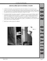
Page 12: ...TRUCTIONS 2 Install the door to check the latchbox adjustment When closing the door look between the door and the face of the stove at the latching arm See Fig B Watch to see that the door hook is lif...

Page 13: ...box is adjusted too loosely 4 To adjust the latchbox open the door using the T handle allen wrench to press the finger of latch arm upward until door is released See Fig C Using a 11 32 socket wrench...

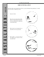
Page 14: ...uring shipping To install the brick follow the directions below 1 Open stove door 2 Place brick A on the left side of the firebox so that it slides into the slots on the top of the firebox and behind...

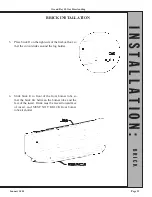
Page 15: ...brick D on the right side of the firebox floor so that the cutout slides around the log holder 6 Slide brick E in front of the front burner tube so that the brick fits between the burner tube and the...

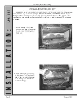
Page 16: ...cause damage to molded holes in bottom of log INSTALLING THE LOG SET CORRECT LOG PLACEMENT IS IMPORTANT TO PREVENT SOOTING The vacuum formed ceramic logs are extremely fragile PLEASE HANDLE CAREFULLY...

Page 17: ...lace ember nuggets across front of burner 5 Light appliance and let logs cure for 30 minutes Adjust shutters to give good flame characteristics NOTE If flame tips have dark yellow or black tips shutte...

Page 18: ...two center screw terminals in the thermostat connection block located at the lower rear of the unit see figure above Turn off the manual switch located on the control panel behind the lower grill REMO...

Page 19: ...supply be sure that the appliance you are installing is designed for the type of gas being supplied to it There is a serial number and listing label on the rear of the appliance that will indicate whi...

Page 20: ...S A requirements and any local codes or regulations of the authority having jurisdiction WARNING This appliance must be installed in an area with an adequate amount of combustion and ventilation air f...

Page 21: ...pen so that it cannot close and pinch or cut the liner Securely attach the flue collar to the liner Adjust and level the stove V E N T I N G M E T H O D S See Page 9 for details See Page 9 for details...

Page 22: ...ich extends to front of stove at top of grill as shown below 3 Turn the appliance on and adjust to highest setting Leave the fan off 4 Wait five minutes then use a match or other device which creates...

Page 23: ...nob slightly and turn clockwise to OFF NOTE Knob cannot be turned from PILOT to OFF unless knob is pushed in slightly Do not force 6 Wait five 5 minutes to clear out any gas Then smell for gas includi...

Page 24: ...it cools down in order not to blow cool air after shut down The operation controls are located on the control panel behind the lower grill and consists of the following 1 The rheostat which controls...

Page 25: ...r to insure they are operating correctly GLASS CLEANING WARNING DO NOT CLEAN GLASS WHEN HOT 1 Turn off pilot 2 Open door WARNING DO NOT USE ABRASIVE CLEANERS ON GLASS OR GOLD SURFACES 3 Using regular...

Page 26: ...1360 SIDE GLASS 842 1280 CENTER GLASS 1 Open and remove stove door Place door on a soft surface 2 Remove rope gasket from door frame 3 With a 5 16 wrench remove all nuts that hold glass retaining bars...

Page 27: ...Grand Bay 40 Gas Freestanding Page 27 January 2000 SCHEMATICS S C H E M A T I C S...

Page 28: ...he unit and turn off gas supply 2 Remove the log set see log installation page 14 for reinstallation 3 Remove the rear log support then remove the eight screws that hold the rear access panel heat shi...

Page 29: ...T WHEN KNOB IS RELEASED A Wait five minutes and try again If the pilot still goes out try again and hold the knob in longer B If the problem persists call your dealer or authorized service person III...

Page 30: ...et and open end wrenches 7 16 socket and open end wrenches 10 mm open end wrench TH20 torque screwdriver Phillips screwdriver Gas Leak Detector Manometer Directions 1 Remove door logs burner tubes nug...

Page 31: ...ide by side with new line and pre bend new line into correct position See Figure E 8 Insert new pilot line into new pilot assembly and tighten fitting with 10mm wrench See Figure F 9 Insert new lox it...

Page 32: ...itting witih wrench 13 Use 3 8 socket wrench to remove existing burner orifices and install new burner orifices See Figure J NOTE Ensure that orifice size for each burner tube and your altitude is cor...

Page 33: ...place manual regula tor See instructions provided with part See Figure M 16 Light pilot and leak test 17 Ignite burners and check HI LO reg ulator for leaks 18 Apply conversion sticker to unit 19 Turn...

Page 34: ...2 0360 Piezo igniter 842 2080 Piezo wire 842 1360 Side H Channel glass 842 1280 Front H Channel glass 842 3090 H Channel Gold Door 842 3100 H Channel Black Door 842 1761 Full view gold door 842 0971 R...

Page 35: ...n Hearth Products will not be responsible for any incidental indirect or consequential damages except as provided by law All electrical components such as but not limited to blowers wiring thermodisc...

Page 36: ...Grand Bay 40 Gas Freestanding OWNER S MANUAL...

Reviews: