Grand Bay 40 Gas Freestanding
Page 18
January 2000
January 2000
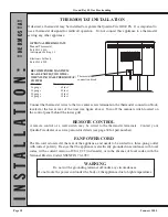
OPTIONAL THERMOSTATS
Manual Thermostat
Part #812-2880
Anticipator Setting 1.2
Electronic Setback
Part #811-0520
RECOMMENDED MAXIMUM
LEAD LENGTH (TWO WIRE)
WHEN USING WALL THERMOSTAT/
SWITCH
Wire Size Maximum Length
16 gauge 65 feet
18 gauge 40 feet
20 gauge 25 feet
22 gauge 18 feet
Thermostat
connection block
IN
S
TA
L
L
A
TI
O
N
:
TH
ER
M
OS
TA
T
THERMOSTAT INSTALLATION
If desired, a thermostat may be installed to regulate the Quadra-Fire GB40 FS. It is important to
use a thermostat designed for millivolt operation. Do not connect this appliance to a thermostat
serving any other appliance.
Connect the thermostat wires to the two center screw terminals in the thermostat connection block,
located at the lower rear of the unit (see figure above). Turn off the manual switch located on
the control panel behind the lower grill.
REMOTE CONTROL
A remote control or a wall switch may be wired to the thermostat terminals. Contact your
Quadra-Fire dealer or service person for details (see page 34 for part number).
FAN POWER CORD
The fan cord is located at the rear of the appliance, and needs to be routed to a three-prong outlet
with correct polarity. Be sure that the appliance is electrically grounded in accordance with local
codes, with a current version of CSA C22 (in Canada), or in the absence of local codes, with the
National Electric Code ANSI/NFPA 70-1987.
WARNING
Do not cut the grounding terminal off under any circumstances.
Do not route the power cord under the body of the appliance due to high temperatures.


