© COPYRIGHT
2008 www.quadlogic.com
© COPYRIGHT
2008 www.quadlogic.com
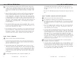
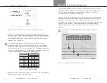
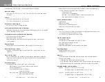
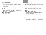
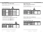
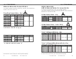
Figure 2-1. Correct CT orientation: H1, dot, or white side facing the line source.
4. Run the CT secondary wires through the conduit to the fuse block. The
secondary wires of the CT may be extended to different lengths depending
upon the gauge of the wire as shown in Table 2-1. For wire runs over 50’
use a shielded, twisted pair. Connect each CT to its proper pair of screw
terminals: X1->I and X2->N.
It is very important that the 2 wires from a particular CT go to the
corresponding pair of screw terminals on the fuse block. For example, if
the black wire (X2) from a CT goes to terminal “NA”, then the white wire
(X1) from that same CT must go to terminal “IA”. The actual arrangement
of the CT connections depends on the installation configuration. Diagrams
of specific installations are located on the following pages.
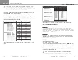
Table 2-1: CT wire extension lengths
5. Repeat items 3 and 4 (above) for each CT until all CTs have been installed
and connected to the MCI screw terminals.
Chapter 2
- RSM-5c and RSM-5 Installation -
5
The following diagrams show the necessary fuse block connections for RSM-5
and RSM-5c meters. Figures 3-1, 3-2, and 3-3 show RSM-5c 3-phase 4-wire
wye, 3-phase 3-wire delta, and 1-phase 3-wire (120/208V, 120/240V, or
277/480V network configuration) respectively.
Figures 3-4 and 3-5 show RSM-5 CL10 3-phase 4-wire wye and 3-phase 3-wire
delta both with High Current Adapters (HCA), respectively. Figure 3-6 shows
the RSM-5 CL10 3-Phase 4-wire wye configuration when using six current
transformers. This allows you to measure two separate electric loads, providing
one set of meter readings. Current transformers must be placed around
the metered wires according to the instructions above to produce accurate
readings.
For specific product offerings please refer to Chapter 9: Ordering
Information.
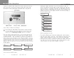
Figure 3-1. 3-Phase 4-Wire Wye Fuse Block Connections.
Fuse Block Connections
Chapter
3
6
#24
#22
#20
#18
#16
#14
#12
#10
3
5
8
13
21
34
53
85
35
55
88
140
223
355
562
893
Wire Size (AWG)
0.1A CT
Length (feet)
5A CT
Summary of Contents for RSM-5
Page 1: ...Table of Contents Manual 3 Phase kWh 3 Phase Demand Single Phase kWh ...
Page 2: ...RSM 5c RSM 5 Installation Manual Power Line Communications Metering Systems ...
Page 23: ......
Page 25: ...3 Phase kWh ...
Page 26: ......
Page 27: ......
Page 28: ...3 Phase Demand ...
Page 29: ......
Page 30: ......
Page 31: ...Single Phase kWh ...
Page 32: ......
Page 33: ......


