background image

9

INSTALLATION

Hard Ceilings

NOTE:

 Installation into a hard ceiling requires that you first 

ensure that the location is suitable and that there are no obstacles 

behind the ceiling material. Use EXTREME CAUTION when cutting 

into hard ceilings to avoid severing electrical wiring, heating ducts 

or water pipes.

Step 1

Carefully unpack the contents of the box and ensure that all parts 

are accounted for before beginning installation.

Step 

Locate the cardboard mounting template and use it to mark the 

hole size needed for the installation. Cut the mounting hole using a 

suitable saw.

Step 

Once the hole is cut, insert the split C ring by twisting slightly and 

rotating it into the hole. Center the C ring around the opening.

Step 

Remove the screws holding the terminal cover plate and then  

remove any knock outs needed to connect the speaker wiring.

Step 

Select the appropriate impedance using the push-button switch 

inside the terminal box if the speaker is part of a low impedance 

system (except C4T and C4-16).

Step 6

Lift the speaker to the ceiling and terminate the wiring to the  

terminal strip. Replace the cover plate and screws.
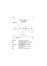
CEILING

C-RING

STEP 3

STEP 4

Summary of Contents for C4 - REV 1

Page 1: ...C O N C O U R S E C S E R I E S INSTRUCTION BOOKLET MODELS C4 C4 16 C4 T C6 C8 CSUB F O R T H E C L O S E S T A P P R O A C H T O T H E O R I G I N A L S O U N D R E V 1 ...

Page 2: ...llation and use of these products Liability is limited to replacement of product or refund at the QUAD Industrial s discretion Your rights to compensation may vary by ter ritory consult with your local QUAD Industrial office or distributor Warranty Service These products are designed to be used as specified and are warranted to be free from defects in materials or workmanship Warranty terms and co...

Page 3: ...er included Concourse C6 The Concourse C6 is a two way ceiling mounted speaker system consisting of a 6 cone low frequency driver and a 1 soft dome tweeter Speakers are packed in pairs and come complete with a tile backing C ring mounting support rails plastic paint covers and cardboard cutout templates Concourse C6 Selectable 4Ω 16Ω 70V 100V operation 50W transformer included Concourse C8 The Con...

Page 4: ...with restraint 2 Split C ring backing plate 2 Support Rails 4 Plastic paint cover 2 Cardboard cutout template 2 Please ensure that you are familiar with all of the parts and how they are assembled before commencing the installation GRILLE GRILLE TETHER LF DRIVER HF DRIVER POWER TAP SWITCH BEZEL ...

Page 5: ...e bezel A metal split C ring is provided to distribute the clamping pressure evenly along the ceiling sur face A pair of metal mounting support rails are provided for added support when the speakers are installed in a suspended tile ceiling A seismic restraint point is provided on the rear of the speaker to facilitate attachment of a restraint tether to the building s structure The removable front...

Page 6: ...course C4 C4 8 C4 16 C4 T Concourse C6 Concourse C8 Concourse CSUB 219mm 8 62 219mm 8 62 349mm 13 74 331mm 13 03 371mm 14 6 238mm 9 37 293mm 11 54 333mm 13 11 212mm 8 35 252mm 9 92 212mm 10 04 295mm 11 61 ...

Page 7: ...e over top of the assembly ensuring the tile is resting on the speaker bezel Step 4 Place the mounting rails on the ceiling tile on either side of the speaker assembly ensuring that they are oriented correctly to provide support by resting on the tile mounting grid when installed in the ceiling Step 5 Place the C ring over top of the speaker assembly and align it with the mounting rails Using the ...

Page 8: ...assembled speaker and ceiling tile into the ceiling grid ensuring that the mounting rails are resting correctly on the grid Step 11 Set the correct wattage tap except C4 16 using the front mounted rotary power switch NOTE The switch is labeled for both 70V and 100V power taps ensure you select the correct tap for the connected amplifier Step 12 If the speaker bezel is to be painted place the suppl...

Page 9: ...use it to mark the hole size needed for the installation Cut the mounting hole using a suitable saw Step 3 Once the hole is cut insert the split C ring by twisting slightly and rotating it into the hole Center the C ring around the opening Step 4 Remove the screws holding the terminal cover plate and then remove any knock outs needed to connect the speaker wiring Step 5 Select the appropriate impe...

Page 10: ...ge tap except C4 16 using the front mounted rotary power switch NOTE The switch is labeled for both 70V and 100V power taps ensure you select the correct tap for the connected amplifier Step 9 If the speaker bezel is to be painted place the supplied clear plas tic paint cover over the front Otherwise attach the grille restraint tether by inserting the plastic plug into the hole on the inside of th...

Page 11: ...ote that one side of the switch is labeled for 70V operation and the other side for 100V systems Ensure that the power is set for the correct amplifier connected NOTE DO NOT USE THE 0 SETTING WHEN CONNECTED TO A 100V SOURCE Select the power tap by dividing the amplifier s available power by the number of speakers to be connected and then selecting the next lower wattage tap For example 300W amplif...

Page 12: ...Speakers in Parallel 8 4 2 Number of 8Ω Speakers in Parallel 4 2 1 Number of 4Ω Speakers in Parallel 2 1 NO MODELS C4 8 C4 16 The C4 8 and C4 16 are fixed impedance models offering 8Ω and 16Ω impedance respectively They are designed for direct connection to low impedance power amplifiers in applications that require relatively few speakers located in close proximity to the amplifier Connect multip...

Page 13: ... 4 16Ω 4 16Ω 4 16Ω 16Ω Transducers LF Driver Size 4 Cone 6 Cone 8 Cone 10 Long Throw 4 Cone MID Driver Size ø ø ø ø ø HF Driver Size 1 Soft Dome 1 Soft Dome Tweeter 1 Soft Dome ø 1 Soft Dome Tweeter Tweeter Tweeter Tweeter Crossover Frequency 2 2kHz 2 5kHz 2 3kHz 150Hx LPF 2 2kHz Enclosure Material Plastic ABS Plastic ABS Plastic ABS Plastic ABS Plastic ABS metal can metal can metal can metal can ...

Page 14: ...rica Inc 8440 154th Avenue NE Redmond WA 98052 U S A C O N T A C T p h 8 7 7 4 4 0 0 8 8 8 p h 4 2 5 8 6 1 3 9 0 9 f x 4 2 5 8 6 1 3 9 0 6 U K C O N T A C T p h 0 8 4 5 4 5 8 0 0 1 1 p h 4 4 0 1 4 8 0 4 4 7 7 0 0 f x 4 4 0 1 4 8 0 4 3 1 7 6 7 O U T S I D E U S A U K p h 8 6 0 7 5 5 8 2 0 9 6 6 3 9 f x 8 6 0 7 5 5 8 2 0 9 0 2 0 3 W E B w w w q u a d i n d u s t r i a l c o m ...

Reviews: