background image

14

Use: 

General Use Guidelines and Preset Description

NOTE! The factory setting for all eight presets is wire-through.
Signals are passed from input to output without any processing.
You may select configurations from the sample files (*.cfg)
within Signal Manager or create your own.

Factory Presets

This is a professional level DSP product that allows the user to

produce virtually unlimited signal processor variations and

configurations. Because of the infinite configuration possibili-

ties of digital signal processing, it is possible to create configu-

rations that may result in unwanted signals or uncontrollable

output.

The Signal Manager software has no way of knowing if the

DSP configuration you have designed will produce the results

you intend. You can create signal loops in a configuration that

may oscillate and damage your sound system if applied to the

unit.  When applying an untested configuration or when

designing or experimenting with this unit, it is a very good idea

to turn down the amplifier’s physical gain controls.  That way,

you won’t damage your speakers or create very loud sounds if

you apply a configuration that doesn’t do what you thought it

would.

IMPORTANT! Please read before operating this Digital Signal Processor with your audio system.

As a general rule, DO NOT CREATE SIGNAL LOOPS!  Do not mix

the output of a DSP object back into its own input!  There is

nothing useful to achieve by doing this, you will only create an

oscillator that could damage your speakers.  Also, USE THE

SINE AND NOISE GENERATOR OBJECTS WITH GREAT CAU-

TION!  These functions produce signals that can harm your

speakers.  Start with lowered gain settings.  If you don’t hear

a signal when you think you should, DO NOT INCREASE THE

GAIN!!!  If the signal isn’t audible at lower levels, there is

something else wrong.  Turning up the gain to full exposes you

and your system to the possibility that some loose connection

somewhere will suddenly send a full-amplitude signal through

your sound system.

Like all freely configurable signal processing tools, this DSP

will do what the configuration your design tells it to do, which

may not be what you expect it to do, so use caution.

General Use Guidelines

Summary of Contents for DSP-30

Page 1: ...1 DSP 30 2 2 XLR Rack mount 2 Channel Digital Signal Processor TD 000097 00 TD 000097 00 Rev B Hardware Manual...

Page 2: ...esidential area is likely to causeharmfulinterference inwhichcase the user will be required to correct the interference at his or her own expense SAFEGUARDS Electrical energy can perform many useful f...

Page 3: ...rol Indicator and Connector Descriptions 12 General Use Guidelines 14 Presets 15 How to save presets into the DSP 30 15 How to recall Presets 16 Lockout feature use 17 Contact closure Feature 18 RS 23...

Page 4: ...0 will mute Overview Front Panel Power switch Signal indicator LED s Multi segment LED numeric display Browse button Accept button RS 232 connector Rear Panel reconfigure and unmute in a fraction of a...

Page 5: ...5 Introduction Illustrations and Dimensions Dimensions...

Page 6: ...sor 1 2 Self adhesive rubber feet 4 3 Hardware Manual this document 1 4 Signal Manager Software CD 1 5 IEC Power Cord 3 x 18 AWG 1 6 RS 232 cable 6 ft 1 Rack mount the DSP 30 by support ing it from un...

Page 7: ...n XLR TRS combo connectors They will accept male XLR plugs or TRS tip ring sleeve 1 4 inch phone plugs The audio output jacks are male 3 pin XLR connectors Balanced connection is recommended for all i...

Page 8: ...mper wire UNBALANCED XLR TRS 1 4 inch TS 1 4 inch phone This style of plug automatically connects the negative terminal to shield when inserted in the jack NOTE for above abbreviations TRS tip ring sl...

Page 9: ...ion shown is representa tive of most simple installations The audio sourceoutputs consoleoutput mediaplayer are connected to the DSP s input jacks The audio program material is processed by the DSP an...

Page 10: ...Signal Manager program Refer to the software help file section RS 232 Communication for the proper procedure and software hardware settings that effect RS 232 communications DSP setup and programming...

Page 11: ...t used when the unit is turned off becomes the active Preset again once the power is reapplied This ensures that the system comes up just as it was left last time it was powered down Do not run your a...

Page 12: ...layindicatesthepre set selected The decimal point after thenumber indicates lock modewhen illuminated A steady display indicates the active preset number A flashing display indi cates the pending pres...

Page 13: ...g for at least 3 seconds locks disables the BROWSE key to prevent accidental operation The ACCEPT key must be pressed again and held for at least 3 seconds to unlock theBROWSEbuttonsothatotherpresetsm...

Page 14: ...oturndowntheamplifier sphysicalgaincontrols Thatway youwon tdamageyourspeakersorcreateveryloudsoundsif you apply a configuration that doesn t do what you thought it would IMPORTANT Please read before...

Page 15: ...our use Modify and save them as your own configurations if they prove useful in your applications You may also create your own to precisely fit your audio system Once a configuration has been created...

Page 16: ...button must be pushed to confirm the selection Press ACCEPT once and the display will change from flashing to steady illumination The ACCEPT button must be pushed within 30 seconds of preset selection...

Page 17: ...OCKED LOCK INDICATOR illuminated when locked TO UNLOCK FRONT PANEL BUTTONS 1 Press and hold the Accept button for at least three seconds 2 The Lock indicator will extinguish 3 The Browse button is ena...

Page 18: ...objects in a DSP configu ration will be triggered by the one contact closure It is not possible to trigger switched gain objects individually This feature requires the construction of a simple RS 232...

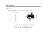
Page 19: ...on the DSP Note Pin 9 is used for contact closure input This pin is not normally used by RS 232devices SomelaptopanddesktopcomputerCOMportshavebeenobservedto pull pin 9 to ground this will cause unex...

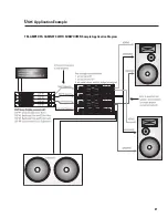
Page 20: ...h pass filter with a 3dB point of 6 kHz and high speed limiters to protect them from transients DSP 2 as signed to midrange drivers might be set for a band pass filter with 3 dB points at 1 kHz and 7...

Page 21: ...21 Use Application Example TRI AMPED PA CABINETS WITH SUBWOOFER Sample Application Diagram...

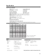
Page 22: ...t impedance 600 Ohms balanced RS 232 Port Note Specifications are subject to change without notice Contact Closure Input sense Inputs 1 discrete input TTL compatible pin 9 of RS 232 port Configuration...

Page 23: ...3 9 s m r B d 5 6 V 0 0 9 t u O V 0 9 9 s m r V 0 3 9 s m r B d 5 0 V 0 0 8 1 t u O V 0 5 7 1 s m r V 0 2 6 s m r B d 0 9 V 0 5 1 n I V 5 6 1 s m r V 0 7 4 s m r B d 0 9 V 0 0 4 n I V 9 3 4 s m r V 0...

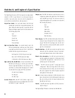
Page 24: ...posewhichshall be CMOS TTL signal compatible Compressor The DSP shall provide a signal compressor that is assignableanywhereinthesignalchain Itshallbebased upon the RMS signal level The compressor sha...

Page 25: ...e 714 957 7100 or 800 854 4079 toll free U S A only Technical Services 714 957 7150 or 800 772 2834 toll free U S A only ADDRESS QSC Audio Products Inc 1675 MacArthur Boulevard Costa Mesa CA 92626 146...

Page 26: ...26 Notes...

Page 27: ...27 Notes...

Page 28: ...California 92626 USA PH 714 754 6175 FAX 714 754 6174 Copyright 2001 QSC Audio Products Inc QSC is a registered trademark of QSC Audio Products Inc Costa Mesa CA QSC and the QSC logo are registered wi...

Reviews: