


10
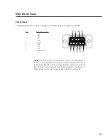
Connecting to the RS-232 Port
Connect to the RS-232 port using the 9-pin serial data cable (included in the shipping box). Orient the DB-9 plug correctly,
insert the plug fully into the RS-232 port and finger-tighten the retaining screws. The cable length should be 25 feet or less.
“Null-modem” type cables will NOT work.
Connection to the computer is required only while loading the presets into the DSP-30 or for “real-time” adjustments to a
configuration before saving it as a Preset. Communication is established using the Signal Manager program. Refer to the
software help file section, “RS-232 Communication” for the proper procedure and software/hardware settings that effect
RS-232 communications.
DSP setup and programming takes place through the RS-232 port. Any time you need to load different presets, connect to
the computer using the RS-232 port. If “real-time” control is required, the RS-232 port connection is required. If you do not
need real-time control, then you can disconnect the serial port after loading the presets. The eight preset configurations
will remain in memory and can be recalled by using the front panel buttons as described on page 16.
RS-232 port connection
Installation:
Connecting to the RS-232 Port