5
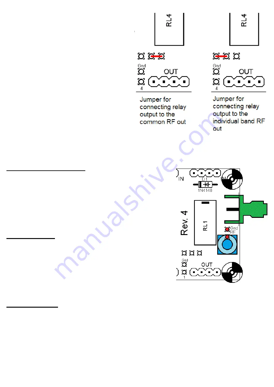
The common RF output is available at the left and
right sides of the board. It is also connected to the
Band 0 output, the output of the Band 0 relay on
the main U3 board. Separate outputs Band 1 to
Band 5 are indicated on the diagram. The output
of each relay can be connected either to the
common RF output, or to the corresponding
individual band output.
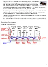
The selection of common RF out or the individual
band output is achieved with jumper wires, in the
blue circled areas in the above diagram. The
centre connection should be wired to either the
right (for common RF out) or the left (for individual
band output). The example diagrams to the right
illustrate the connections for each case, for Band
4.
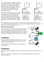
For the simple case, matching the earlier PCB revision 1, when all relay outputs are connected to the
same common antenna (the common RF Out), jumper all the central pads of each three, to the pad to its
right. This is shown in the left diagram, above.
SMA Connector for RF Output
The Rev 4. PCB features pads for soldering an SMA connector for
the common RF Output, if you wish, at the right side of the PCB.
There are pads for an edge-fitted SMA connector (shown coloured
green) or a vertical fitted type (blue). Alternatively you may still use
the existing two connection pads (Red-coloured, 0.1-inch pitch).
5. Operation
When used with the Ultimate3 kit, firmware version v3.02 or above
is required. Please refer to the appropriate operation manual for
your firmware version, for details.
The relay-switched LPF kit may also be used with the QRP Labs
Arduino shield kit.
6. Resources
Please see the kit page http://www.hanssummers.com/ultimatelpf for information on latest updates and
issues.
Please join the Yahoo forum http://groups.yahoo.com/neo/groups/QRPLabs/info for discussion and
updates on all the kits!


