background image

INSTALLATION AND OPERATION MANUAL SOLAR MODULES Q.PEAK DUO XL-G11S.X / BFG

23

5 Grounding

Protective Grounding

In order to prevent electrical shock or fire, the frame of the mod-
ule as well as any non-current-carrying metal parts of the system 
must be grounded. While this section provides some informa-
tion about grounding the Qcells frames and modules, reference 
should be made to local statutes and regulations for specific 
requirements on grounding. The U.S. National Electrical Code ad-
dresses these issues in Article 250. A module with exposed con-
ductive parts is considered to be in compliance with this standard 
only when it is either electrically grounded in accordance with the 
manufacturer’s instructions and the requirements of the National 
Electrical Code, ANSI/NFPA 70 (2014-2017), or when the bonding 
means has been evaluated with this module to UL 2703.

Proper grounding is achieved by bonding all exposed non-cur-
rentcarrying metal equipment to the appropriately sized equip-
ment grounding conductor (EGC) or racking system that can be 
used for integrated grounding.

Qcells frames are protected from corrosion with an anodized 
coating, which has to be penetrated in order to ensure proper 
bonding. The different methods listed below are suggested 
methods for an appropriate bond between the frame and the 
EGC or racking system (that will have to be properly grounded). 
The method appropriate for any individual installation will depend 
on multiple factors.


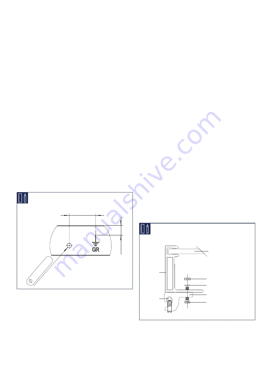
Dimensions shown are in inches.

0.177” (+0.008/-0)

±0.08

0.79”

0.47”

±

0.08

Option A: Use of a grounding lug

A listed grounding lug can be bonded to the frame using the 
grounding holes pre-drilled in the frame. These holes are marked 
with a ground symbol, as shown below on the frame section 
drawing: To install the grounding lug, follow the specified instruc-
tions of the manufacturer. The grounding lug should be made of 
stainless steel or tin plated metals such as aluminum to avoid cor-
rosion.

The grounding lug should be attached to the frame grounding 
hole using a stainless steel screw, toothed lock washer or KEPS 
nut (in order to penetrate the anodized layer) and backing nut. 
Care should be taken to avoid the use of grounding hardware of 
dissimilar metals, which may lead to corrosion.

Option B: Integrated grounding methods

The Qcells modules can be bonded with the racking system us-
ing UL1703 or UL2703 certified integrated grounding methods. 
The racking system will then have to be grounded so that the 
overall system is properly grounded. The listed racking system 
and grounding device should be installed in accordance with 
the manufacturers’ instructions. An example of such integrated 
grounding method is the use of a WEEB clip or Schletter plate 
between the module and the racking system, when mounting the 
module.

The WEEB washers are generally compatible with Qcells mod-
ules, however each combination module / racking system requires 
a specific WEEB washer size. Note that WEEB clips are intended 
for single use only; they must not be reused after removal or 
loosening. Refer to Wiley’s installation instructions for the specific 
use of WEEB washers.

An example of such integrated grounding method is the use of a 
washer recognized as meeting UL2703 requirements between 
the module and the racking system, when mounting the module. 
For example, WEEB washers are generally compatible with Qcells 
modules, however each combination module / racking system 
requires a specific WEEB washer size. Note that WEEB washers 
are intended for single use only; they must not be reused after 
removal or loosening. Refer to Wiley’s installation instructions for 
the specific use of WEEB washers.

PV Laminate

Backing Nut (Stainless Steel)

Toothed Lock Washer (Stainless 
Steel)

Grounding Lug (Stainless Steel 
or tin-plated metal)

Equipment 
Grounding 
Conductor

Aluminum 
Frame

Screw (Stainless Steel)

Summary of Contents for Q.PEAK DUO XL-G11S.X / BFG Series

Page 1: ...Installation and operation manual Q PEAK DUO XL G11S X BFG solar module series ...

Page 2: ...ant module was manufactured apply to the installation mounting and maintenance procedures for the respective solar modules as far as no updated document is provided 1 Introduction 3 2 Planning 5 2 1 Technical specifications 5 2 2 Requirements 6 2 3 Mounting options 8 2 4 Electrical layout 14 3 Installation 15 3 1 Safety and transport 15 3 2 Preparation of installation 17 3 3 Module installation 18...

Page 3: ...Beware of possible danger or damage Categories Danger Risk of fatal injury Attention Risk of serious injury or damage to property Note Risk of damage to product Units Where both Imperial and U S units for example inches are shown metric units are definitive References to Data Sheet or Module Data Sheet refer to the Module Data Sheet applicable to the module being used Safety Regulations The instal...

Page 4: ... for the entire life of the solar power system Please contact your system supplier for information concerning the formal requirements for solar power systems Please be sure to contact the relevant local authorities and en ergy providers regarding regulations and permit requirements prior to installation of the solar power system Your financial success depends on the fulfillment of these requiremen...

Page 5: ...ype 3 but with metallic frame Max test load Push Pull1 lbs ft 113 50 5 400Pa 2 400Pa Max design load Push Pull1 lbs ft 75 33 3 600Pa 1 600Pa Middle rail No Certificates Quality Controlled PV by TÜV Rheinland CE compliant IEC 61215 2016 IEC 61730 2016 PV module classification Class II 1 Test and design load in accordance with IEC 61215 2016 depending on mounting options see section 2 3 Mounting opt...

Page 6: ...e with IEC 61215 and Design Load 1 5 in accordance with UL 61730 Installation using a mounting structure for solar modules Mounting Structure Requirements Requirements for the mounting structure Conform to the necessary structural requirements Compliant with local snow and wind loads Properly fastened to the ground the roof or the façade Forces acting on the module are relayed to the mounting subs...

Page 7: ...AR MODULES Q PEAK DUO XL G11S X BFG 7 75 3 Maintain the permissible angle of inclination Minimum angle of inclination 3 Inclination angles above 75 may be limited by local regulations Standing water on the modules glass needs to be avoided ...

Page 8: ...or avoided by technical measures A minimum support depth of 0 59in 15mm is required on the back side of the module Loads according to IEC 61215 2 2016 and UL 61730 2 2017 except for design loads lower than 1600 Pa which do not fulfill the requirements of the standards The test procedure is always according to IEC 61215 2 2016 Design loads result from the safety factor 1 5 Mounting options with cla...

Page 9: ...a DESIGN LOAD PUSH PULL Pa L 15 8 21 7 400 550mm 3600 2400 2400 1600 S 0 79 20mm 2400 2400 1600 1600 L 27 6 700mm CL3 Ensure that module frame is fixed directly on the rail of the substructure no spacer allowed between the module and substructure Minimum support depth of 0 59 in 15 mm is required on the back side of the module CL5 Minimum required support depth on the module backside is 0 39in 10m...

Page 10: ...he module and substructure Use M8 corrosion proof screws and washers diameter 0 62in 15 8mm for mounting slots Detail A Fig 1 and M6 corrosion proof screws and washers or bobtails for tracker slots diameter 0 51in 13mm Detail B Fig 1 Mounting screws and washers should have the same material properties 4 BOLTS SCREWS ON LONG SIDE 2 CONTINUOUS RAILS UNDERNEATH LONG FRAME PARTS mFB2 L POSITION OF BOL...

Page 11: ...washers or bobtails for tracker slots diameter 0 51in 13mm Detail B Fig 1 Mounting screws and washers should have the same material properties TRACKER INSTALLATION USING 31 1in 790mm HOLES TB1b L Torque tube TB2b L1 L2 Torque tube POSITION OF BOLTS in TEST LOAD PUSH PULL Pa DESIGN LOAD PUSH PULL Pa POSITION OF BOLTS in TEST LOAD PUSH PULL Pa DESIGN LOAD PUSH PULL Pa L 32 9 836mm 2600 2300 1700 150...

Page 12: ...CLAMPS TC1 L POSITION OF BOLTS in TEST LOAD PUSH PULL Pa DESIGN LOAD PUSH PULL Pa L 40 6 42 6 1031 1081mm 1800 1800 1200 1200 TC1 Ensure minimum support depth of 0 47in 12mm on the backside and 0 39in 10mm on the front side of the module Distance between outer edge of module and middle of the clamp 2 Planning 2 3 Mounting options ...

Page 13: ... the limited area where the substructure element is located beneath the module see figure 2 and 3 Fig 3 Push loads in relation to minimum clearance between frame bottom edge and substructure 2 Planning 2 3 Mounting options Specifications for TB1a TB1b TB2a TB2b and TC1 Mounting Options 100 257 257 100 100 120 160 160 Limited area 1 mm Limited area 2 mm CLEARANCE mm TEST LOAD Pa Limited Area 1 Limi...

Page 14: ... system voltage as listed in the applicable data sheet Take into account all possible operating situations and all rel evant technical norms and regulations when designing the system It has to be ensured that the maximum system voltage including all necessary safety margins is not exceeded Take the voltage limit of the inverter into account when deter mining the maximum number of modules in the st...

Page 15: ... modules in their original packaging until instal lation Store the modules securely in cool and dry rooms The packaging is not weatherproof Ensure that all personnel are aware of and adhere to accident prevention and safety regulations While working wear clean gloves GB I D Danger Risk of fatal injury due to electric shock Do not install damaged modules Inform your distributor of any damages immed...

Page 16: ...ndi tioning systems Note Module damage may occur Do not drop modules Note Module damage may occur Only make modifications to the module which have been confirmed in writing by Qcells confirmation letter Note Module damage may occur Never lift or move the module with the connection cables or junction box Carry modules upright and horizontally as shown Note Module damage may occur Never step on modu...

Page 17: ...k of fatal injury due to electric shock Ensure that modules and tools are not subject to moisture or rain at any time during installation Warning Risk of injury due to falling modules Secure modules during installation Do not install modules in windy or wet weather Danger Risk of fatal injury due to electric shock Only use dry insulated tools Do not carry out the installation alone Only install un...

Page 18: ...ing optoins Tighten clamps according to manufacturer s instruc tions Maintain an interval of at least 0 39in 10mm be tween two modules along the short side and 0 20in 5mm along the long side Note Module damage may occur Do not subject modules to mechanical tension Max torsion 0 12in ft 10mm m Option 2 Install the module at the 4 mounting points see see section Mounting options with bolts of chapte...

Page 19: ...nd safety guide lines for the installation of electrical devices and systems Please make sure to take all necessary safety precautions With module or phase voltages of more than 120V the safety extra low voltage range is exceeded Carry out work on the inverter and the wiring with extreme cau tion Ensure that the modules are disconnected at the inverter prior to separation Be sure to observe the ti...

Page 20: ...isk of fatal injury due to electric shock Never plug or unplug the cable when under load Modules must not carry any current 1 Switch off the inverter OFF EN 2 Switch off the DC circuit breaker 3 Measure shutdown in DC String no DC current flow 4 Disconnect plugs by the use of appropriate and qualified tools of the manufacturer 5 When connecting the modules proceed in reverse order Danger Risk of f...

Page 21: ... electric shock Ensure that all electrical components are in a proper dry and safe condition SOLAR click Ensure for a tight connection between the plugs Plugs click together audibly Do not connect modules with different orientations or angles of inclination in the same string Note Module damage may occur Ensure that the cabling is not under mechanical stress Comply with bending radius of 2 36in 60...

Page 22: ...n dards Note Module damage may occur Ensure that the plug connections are secured away from any water channelling surface Integrate the system into the existing lightening protection system in accordance with the applicable local regulations Warning Fire Risk Do not use light concentrators e g mirrors or lenses Ensure that the cabling is not exposed and or hang ing and is protected from dirt moist...

Page 23: ...ions of the manufacturer The grounding lug should be made of stainless steel or tin plated metals such as aluminum to avoid cor rosion The grounding lug should be attached to the frame grounding hole using a stainless steel screw toothed lock washer or KEPS nut in order to penetrate the anodized layer and backing nut Care should be taken to avoid the use of grounding hardware of dissimilar metals ...

Page 24: ...e to electric shock Do not attempt to fix any problems yourself e g glass cracks damaged cables Please contact an installer or Qcells Technical Customer Ser vice Department 7 Disposal Do not disconnect modules by yourself Please commission a trade specialist Dispose of modules in accordance with the local disposal reg ulations ...

Page 25: ...cratch off dirt Module cleaning has to be done by qualified personnel ac cording to the state of the art and taking into account all rele vant safety issues and general product properties e g but not restricted to electrical safety mechanical stability load limits depending on the actual mounting options chemical suitability no effect to any of the module s compo nents e g cable connector silicone...

Page 26: ...Installation manual solar modules Q PEAK DUO XL G11S X BFG_modules_series_2023 03_Rev04_NA HANWHA Q CELLS AMERICA INC 400 Spectrum Center Drive Suite 1400 Irvine CA 92618 USA EMAIL WEB TEL hqc inquiry qcells com www qcells com 1 949 748 59 69 ...

Reviews: