background image

38

39

CHAPTER 4  MENUS

PICTURE 4-14

PICTURE 4-15

PICTURE 4-16

Audio/Video

 – Selecting this box adds an audio feed (if you have a microphone located at 

or near the camera). On the Extra Stream, you can enable the  Audio (first box in that 
column) only if the Video box is also toggled.

Overlay

 – This window allows you to mask off areas from view.  This is useful in 

circumstances such as when a camera’s field of view includes a combination lock or 
other similar situation.

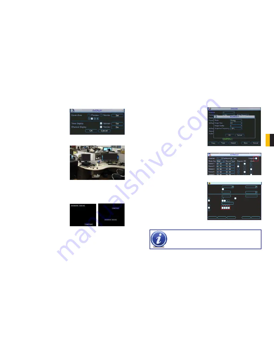
You can mask up to four areas in each 
camera’s field of view in two modes. Preview 
mode blocks the area for both local and 
network viewers. Monitor allows the local 
user to view the area but remote viewers 
cannot see the area. These privacy blocks 
affect both the live view and playback. You 
can select either or both allowing you to 
block selected areas for one set of viewers 
but not others.
Clicking any of the numbered boxes will 
create a black area in the upper left corner of 
the screen. If you select more than one, they 
will all be located in the same place. Clicking 
on the 

Set

 button will hide the 

Overlay


window and give you a view of that camera’s 
video feed along with the black box(es). The 
active box will be outlined in green and you 
can switch between boxes by clicking on 
another one. Each box will have its number 
inside. It can be moved and sized as needed 
using the mouse.  Right-clicking on the 
screen will return you to the 

Overlay

 window.

Time Display

 – This allows you to display the 

system time on the channel’s screen 
during playback or not. In addition, 
by clicking the 

Set

 button, the time 

display can be relocated anywhere on 
the screen by clicking and dragging. 
A “Before” and “After” example is 
shown in 

Picture 4-16

.

Channel Display

 – Like time display, this toggles the appearance of the channel’s number on 

the screen during playback as well as allowing it to be repositioned in a similar fashion.

SNAPSHOT

In addition to taking video of an event, the DVR can be set to record - and transmit - still 
images from whichever cameras you select in the 

Schedule

 and 

Detect

 windows which are 

covered in 

Sections 3.6

 and 

4.7

 respectively. 

The actual settings for the Snapshot feature are configured in the 

Snapshot

 window which 

can be opened by pressing the 

Snapshot

 button in the 

Encode

 window.

PICTURE 4-17

PICTURE 4-18

PICTURE 4-19

Mode

 - You can chose to have each camera 

take a snapshot based on 

Timing

 or 

Trigger

Image Size

 - 

D1

 produces an image twice 

the size of 

CIF

 . You can chose to 

use a different format for snapshots 
than the format that camera is 
configured to record video.

Image Quality

 - With a range of 1 to 4, this 

controls the quality of the snapshot(s). 
A setting of “4” provides better 
images, but at an increased file size. 
You may have to lower the quality 
if the file size exceeds your e-mail 
in-box’s capacity.

Snapshot Frequency

 - This will allow you to 

take 1-7 shots in sequence.

Each camera can be individually configured. 
These settings are what will be used when 
you enable the 

Snapshot

 feature in any 

window that offers that option. Examples 
are highlighted with Red Boxes in 

Pictures 

4-18

 and

 4-19

.

NOTE!

  It  is  possible  to  have  the  Snapshot  feature  set  to  occur  both  on 

schedule  and  when  triggered  by  an  event  such  as  Motion  Detection.  The 
triggered activation will take priority over the scheduled event. 

DETECT

Event Type
Enable
Region

Period

Delay

Show Message         Alarm upload         Send Email
Record Channel

Tour
Snapshot
Buzzer

Anti-dither

sec.

Channel

Sensitivity

Motion Detect

1

3

0

sec.

10

Select

Set

Copy

Paste

Default

Save

Cancel

1 2 3 4

1 2 3 4
1 2 3 4

Summary of Contents for QC444

Page 1: ...1 H 264 NETWORK DVR Variable CIF and D1 Recording Options User Manual MODEL QC444 ...

Page 2: ...e registration form online In addition to warranty and technical support benefits you ll receive notifications of product updates along with free downloadable firmware updates for your DVR Register today at www Q See com Please see the back of this manual for exclusions This manual is written for the QC444 DVR and was accurate at the time it was completed However because of our ongoing effort to c...

Page 3: ...Motion Detection 26 Video Loss 27 Camera Masking 27 Event Response 27 3 8 Backup 29 4 MENUS 31 4 1 Main Menu 32 4 2 Info Menu 32 HDD Information 32 BPS 33 Log 33 Version 34 Online Users 34 4 3 Setting Menu 35 Encode 37 Snapshot 39 Schedule 40 Network 40 Default 41 4 4 Advanced 42 HDD Manage 42 Abnormality 43 Record 43 Account 43 Auto Maintainenance 44 TV Adjust 44 4 5 Backup 44 4 6 Shutdown 44 5 H...

Page 4: ... this DVR without the cover securely in place Do not attempt to do any repairs to the DVR yourself If there are unusual sounds or smells coming from the DVR unplug it immediately and contact Q See technical support Under no circumstances should the cover be removed while the device is connected to a power source You should only remove the cover to install replace the hard disk drive See Chapter 5 ...

Page 5: ...ilt in USB port gives you the option of backing up and transferring your video footage using a flash drive or external USB hard drive You can also connect to an external CD DVD writer to burn your file footage right onto a compact disc or DVD disc Files can also be accessed from your DVR system to a remote computer location by logging on remotely Connect to a TV or PC Monitor Easily This system co...

Page 6: ...tatus Lights Alarm Not functional on this model Net Red light indicates that network connection is lost HDD Red light indicates that hard drive is operating Power Red light indicates that DVR is powered up 8 USB Port For use with flash drive when backing up or updating firmware Not for use with mouse 2 2 REAR PANEL Number Item Function 1 Video In Ports BNC Connectors for video feed from cameras 4 ...

Page 7: ...ontext of where they are used Some examples are LEFT CLICK Selecting an item Opening a menu Checking a box or motion detection status Selecting letters numbers or symbols on the virtual keyboard DOUBLE CLICK Selecting an event for playback Selecting a screen to zoom into from multi screen mode PICTURE 2 3 VIRTUAL KEYBOARD The virtual keyboard is contextual For example it will only show digits when...

Page 8: ...rial number 10 Function Aux Key In 1 channel monitor mode pop up assistant function In motion detection interface functions as a directional key to complete setup Backspace Press for 1 5 seconds to clear all contents in current text box In HDD information interface used to switch between HDD record time and other information Special combined operation in some menus 11 Escape Cancel Go back to prev...

Page 9: ...e side of the DVR The left and right arrows on both the remote and DVR side panel will cycle through which channels are displayed In Live View along with the channel s you will see the system date and time displayed along with the name and icons indicating the status of each channel Setting the system date and time and changing the channel names is covered in Section 4 3 under the Settings menu Di...

Page 10: ...iewing mode as well as moving directly to a selection of menus PICTURE 3 3 PICTURE 3 4 LOGOUT Selecting the Shutdown icon in the Main Menu will open the Shut Down window This window allows you to choose to log out as a user shut down the system restart the system or switch users In addition the DVR can also be shut down by pressing on the front panel power button for three seconds The system will ...

Page 11: ...ched You can also click on the clock icon to open the Calendar Highlighted dates have recorded files PICTURE 3 9 PICTURE 3 10 PICTURE 3 11 PICTURE 3 12 STEP 2 Enter the start time if known or skip this field to search the entire day Select the type of event All Alarm Motion Detection MD or both Alarm and Motion Detection STEP 3 Select which channels you wish to view Each of the four slots is a pul...

Page 12: ...00 00 R 17 00 00 R StartTime Type Start Time 08 19 10 13 20 00 End Time 08 19 10 13 26 00 Size KB 52736 1p 2p 3p 4p Zoom In multi screen playback you may click on a channel to bring it to full screen view Double clicking the screen again will further enlarge the screen and remove the playback bar Double clicking a third time will return you to the multi screen mode You can also step backwards in t...

Page 13: ...tailed and flexible NOTE Motion Detection can also be set up in the Detection menu as described in Section 3 7 If you need the DVR to do more than just record Motion events then follow the instructions in Section 3 7 You do not need to set up motion detection in both menus Channel The first setting is which channel you wish to configure In addition to selecting a channel number you can globally co...

Page 14: ...es and this will reduce false alerts You can click and drag the mouse to turn off multiple blocks at the same time and you can deactivate motion detection in multiple separate areas of the screen To reactivate motion detection simply repeat the process in the deactivated blocks and they will regain their red hue and detect motion as normal You cannot use Copy Paste in Motion Detection because each...

Page 15: ...ing on other cameras Tour This will cause the DVR to cycle through selected channels on the display in live view It will not affect what is recorded Snapshot The DVR is capable of taking still images which can be sent via e mail or FTP See Advanced Network Setup in Section 1 2 of the Remote Monitoring Guide for full instructions 3 8 BACKUP This DVR supports backing up files from the hard drive to ...

Page 16: ...r Minute Second Therefore a file shown on the DVR as being a regular record R being recorded on 01 04 11 starting at 2 00 00 would have a file name of 1_01_R_010411020000 dav The Year Date Month format is the same as you have set in the General interface The files can be played back using the software included on the CD accompanying this DVR MENUS CHAPTER 4 RS232 MAIN MENU Backup Information Setti...

Page 17: ...r the system will come directly to this menu An error may be indicated if the hard drive time and system time do not match To resolve this issue adjust the time in the General setting menu located in the Setting menu See Section 4 3 and restart the system Formatting the drive using HDD Manage as described in Section 4 4 Advanced is another possible solution to drive errors If the drive is damaged ...

Page 18: ... window A total of ten interfaces are available through this menu and they contain most of the functions needed to configure your DVR Additional settings are available in the Advanced menu covered in Section 4 4 In addition to Schedule and Detect which were covered in Chapter 3 available interfaces are General Encode Network Display and Default PICTURE 4 9 PICTURE 4 10 GENERAL This window is where...

Page 19: ... sub stream display referred to as Extra Stream 1 in this window This stream is the data that is sent to remote monitoring devices Due to bandwidth concerns these data streams are generally smaller than those sent directly to the DVR itself These streams run in parallel with the main stream sent to the hard drive and they do not affect each other PICTURE 4 13 Resolution This system supports the D1...

Page 20: ...le is shown in Picture 4 16 Channel Display Like time display this toggles the appearance of the channel s number on the screen during playback as well as allowing it to be repositioned in a similar fashion SNAPSHOT In addition to taking video of an event the DVR can be set to record and transmit still images from whichever cameras you select in the Schedule and Detect windows which are covered in...

Page 21: ... reboot in order for these changes to take place Enable Tour Selecting this box will cause the screen to cycle through displaying channels selected in the following fields Interval This is the time from 5 to 120 seconds that the DVR will display each group of channels before moving to the next group in the tour View These are the number of groups available in each tour Deselecting a number means t...

Page 22: ...rrors as well as how these alarms are handled Each type of alarm can be independently enabled along with what events that type of alarm will trigger ABNORMALITY Event Type Enable Show Message Alarm upload Send Email Buzzer No Disk Save Cancel Event type Chose from No Disk Disk Error Disk No Space Net Disconnected and IP Conflict Latch This is the hold time that the DVR will wait before issuing ano...

Page 23: ...HARD DISK DRIVE CHAPTER 5 Your DVR uses a standard desktop computer SATA Serial Advanced Technology Attachment hard disk drive and will support up to a 2TB terabytes drive These drives are the current industry standard and may be purchased wherever computer parts are sold Depending on where you purchased your DVR it may come with a pre installed drive But we recognize that you may wish to upgrade ...

Page 24: ...e optimal capacity for your purposes the chart below to estimate the size of hard drive that you ll need VIDEO FORMAT RESOLUTION FRAME RATE FPS VIDEO QUALITY BIT RATE kbps SPACE USED MB h NTSC CIF 30 Highest 1M 465 Higher 768k 297 Medium 512k 230 Low 384k 173 Lower 256k 115 Lowest 128k 56 D1 Highest 2M 910 Higher 1 5M 712 Medium 1M 468 Lower 768K 297 Lowest 512K 241 PAL CIF 25 Highest 1M 466 Highe...

Page 25: ...ardware malfunction APPENDIX 8 There is no audio when monitoring Possible Causes a Channel with audio is not full screen make the channel you want to hear audio on full screen b Audio cable is damaged c Combo DVR hardware malfunction 9 There is audio when monitoring but there is no audio when system plays back Possible Causes a Setup is not correct Please enable audio function b Corresponding chan...

Page 26: ... NVIDIA GeForce 8400 ATI RADEON HD3450 Full Direct Draw Support with 512MB Video RAM OS Windows 2000 SP4 above Windows XP SP2 above VISTA Win7 DIRECTX 9 0 COMPONENT MINIMUM REQUIRED CPU Intel P4 2 8G minimum or later Intel processor MOTHERBOARD Intel with Intel system chipset HDD 250GB minimum RAM 1GB minimum VGA Supports MOST AGP and PCI E Video Cards with 128MB of RAM or more with full Direct Dr...

Page 27: ...extreme environmental temperatures humidity lightning and sudden surges of electricity 3 Damage caused by acts of nature e g earthquake fire etc 4 Equipment damage caused by the maintenance of personnel not authorized by Q See 5 Product sold over 12 months ago In order to fulfill the terms of your warranty you must complete the registration process after purchasing our product To do this simply fi...

Page 28: ...54 Digital Peripheral Solutions Inc 8015 E Crystal Drive Anaheim CA 92807 ...

Reviews: