background image


Page: 3 

3.


Initial Power Up 

NOTE 1:

 It is recommended that the Engineer menu is accessed prior to opening a powered Home Panel, as 

being in the Engineer menu will prevent the tamper alarm from triggering. 

NOTE 2

: If any new peripheral is installed (such as: Modem, I/O board or Expander) it is recommended that the 

Home Panel is powered down (mains and battery). 

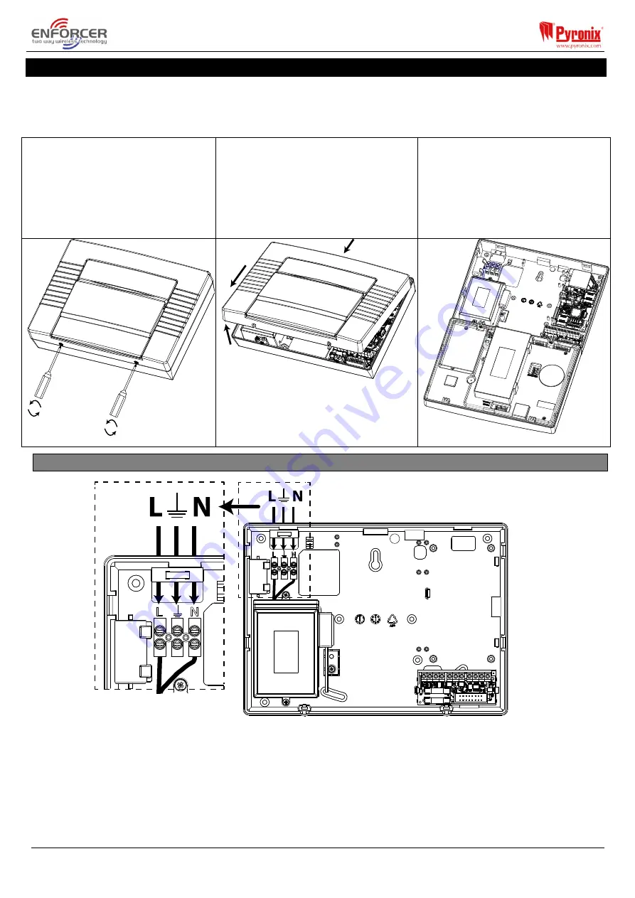
1.

 Slightly unscrew the two screws 

located at the bottom.  

NOTE:

 Do not fully unscrew as these 

can be used as a 'hanger' to the rear 
casing as shown in Step 3. 

2.

 Unhinge the Home Panel 

from the top and pull down to 
disconnect the front of the case. 

NOTE:

 Take extra care when removing 

the front of the Home Panel as 
modems, I/O boards etc may be 
connected to the front. 

3.

 Rotate the front of the 

Home Panel 180 degrees and 
hang it on the opening screws if 
required. 


3.1


Mains and Earth Wiring 

 
It is important that the electrical earth wire is connected before connecting the 230V mains supply to the 
Home Panel. 

NOTE 1:

 Do not locate the mains cables next to internal cabling.  

NOTE 2:

 Ensure that the Home Panel is not mounted on any metal surfaces. 

NOTE 3: 

Mains cables should not be internally 'looped' or tightly bundled as this may interfere with the wireless 

antennas. Where possible it is recommended that all mains cables should be installed through the area nearest the 
mains terminals as shown above. 

Summary of Contents for HomeControl+

Page 1: ......

Page 2: ...red inputs two wireless external sirens 32 keyfobs 75 user codes or tags 20 programmable and automation outputs and a large variety of wireless accessories All devices can cover a wireless range of op...

Page 3: ...front of the case NOTE Take extra care when removing the front of the HomeControl Panel as modems I O boards etc may be connected to the front 3 Rotate the front of the HomeControl Panel 180 degrees...

Page 4: ...installed on an uneven surface 5 If an I O board is installed then this space is used to install it See page 8 3 3 Inside of the HomeControl Panel Front 1 RS232 connection for up downloading to the In...

Page 5: ...Ensure that a readily accessible disconnect device is incorporated into the premises installation wiring and is provided externally to the equipment with a contact separation of at least 3 0mm and co...

Page 6: ...CR123A Battery Type MC2 WE BATT CR3 Battery Type MCMINI WE MC1 SHOCK WE BATT CR123A Environment All Devices Nominal operating temperature 10 C to 50 C Certified operating temperature 10 C to 40 C Stor...

Page 7: ...may look like General Principles NOTE 1 No alarm system cable should be run with other cables carrying AC or digital signals NOTE 2 The cables should be protected by the use of grommets where appropri...

Page 8: ...rd can have on the RS485 bus are as follows 4 x Input Expanders EURO ZEM8 EURO ZEM8 EURO ZEM8 PSU ONE of these can be a wireless ZEM EURO ZEM32 WE 1 x Output Expander EUR OEM16R or EUR OEM16R PSU 4 x...

Page 9: ...If using the EURO PROXI as access control entry control please refer to page 13 5 1 4 Wiring External Readers If an additional external reader is connected this will need to be assigned in the program...

Page 10: ...of the bell box NOTE The input must be programmed as tamper The resistor value is 2K2 as shown in the diagram above IMPORTANT NOTE THE BELL BOX CONNECTED WILL NEED TO BE IN SCB self contained bell MOD...

Page 11: ...ddress the Wireless ZEM as ZEM 0 1 and 2 in the programming function Install ZEM and learn 24 inputs to the system using the Wireless Device Control menu see the Programming Manual for further informa...

Page 12: ...erminal MUST NOT be connected ZEM Address 0 Inputs 35 42 ZEM Address 1 Inputs 43 50 ZEM Address 2 Inputs 51 58 ZEM Address 3 Inputs 59 66 5 1 9 Connecting an Output Expander 1 x Remote Output Expander...

Page 13: ...3 Setting with Entry Control Action Visual Sequence Present a valid tag to the reader and then remove it The door lock will open Present the same tag to the reader within 10 seconds of presenting it i...

Page 14: ...set or the unset symbol will be illuminated if the system is unset Present the same tag to the reader within 10 seconds of presenting it initially and then remove it The doors will unlock and the sys...

Page 15: ...e will start on the control panel The RED LED will illuminate when the system has set and after a few seconds the LED will extinguish 5 3 4 Unsetting with Entry Control Action Visual Sequence Present...

Page 16: ...contract SIM cards Some networks have to enable the data channel separately Some networks use a different phone number for the data GPRS channel from the GSM number of the SIM card Some networks autom...

Page 17: ...mmunicate over a Local Area Network to either InSite the PyronixCloud or to an ARC NOTE The product has been approved as supplied If the communications module is replaced with a different model beside...

Page 18: ...ID and password then go onto your PC or smartphone 2 Connect your device to the control panel WiFi it appears as a local WiFi network and then open a web browser to see the list of connections availab...

Page 19: ...in accordance with the local regulations 6 EN 50131 Terminology Enforcer HomeControl Panel Language EN50131 Language Set Set Unset Unset Day or Unset Mode Unset State may be relevant to a specific ar...

Page 20: ...ouse Braithwell Way Hellaby Rotherham S66 8QY Customer Support line UK Only 44 0 845 6434 999 local rate or 44 0 1709 535225 Hours 8 00am 6 30pm Monday to Friday Email customer support pyronix com Web...

Reviews: