


PureLink
VIP-200 II Quick Start Guide V1.0
6
KVM Operation
The receiver has four USB ports, the first port operates at 1.1 speeds, and the remaining ports operate at
2.0 speeds. Please use ports 2,3 or 4 when using a mouse or keyboard via USB to ensure ultra-low
latency. All receivers are by default enable to connect via USB to the transmitter. You can disable the
USB for each receiver if desired using our utility software, or from the OSD.
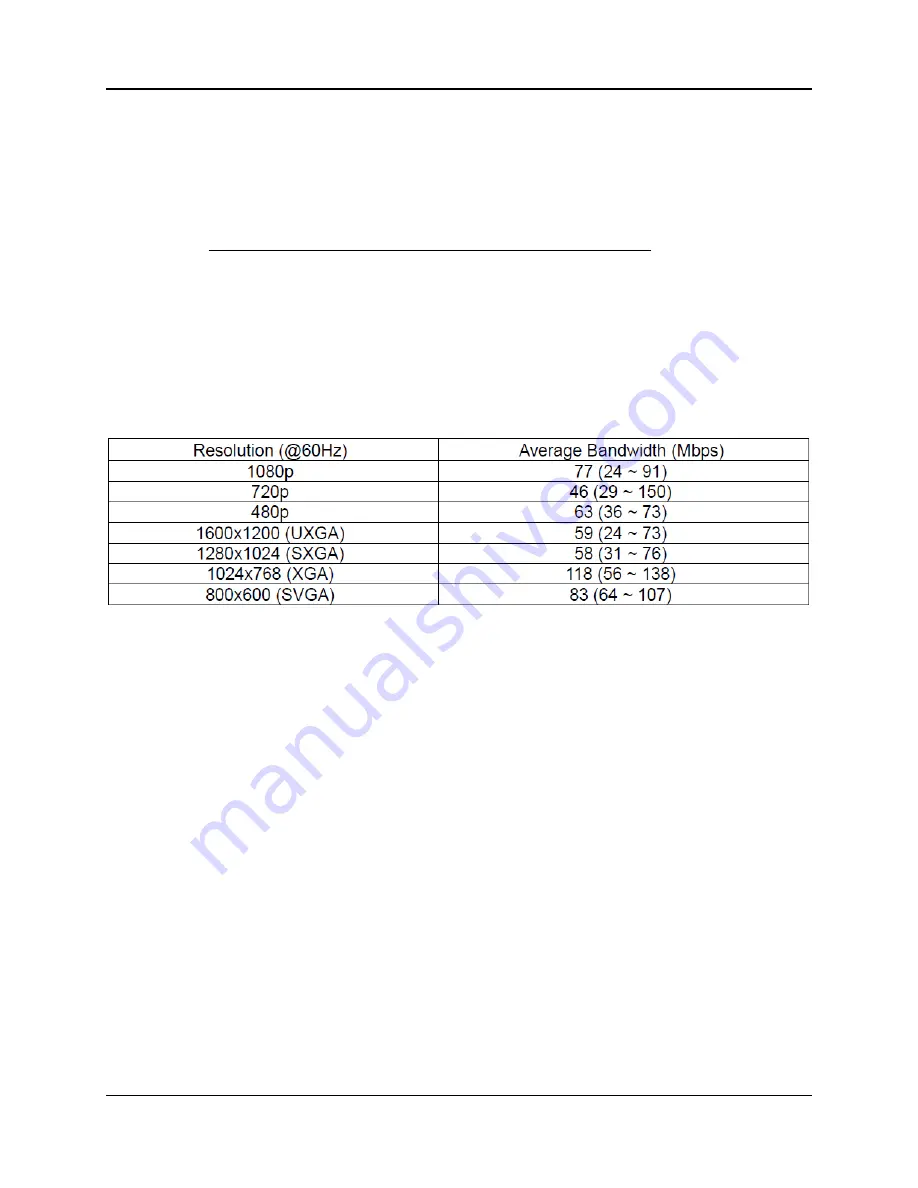
Typical reference streaming rates
Use of USB may add up to 50 mpbs to stream rate, depending on the USB device(s).


