background image

16

5.

Put the basket back into the housing. Be sure to align the notch in the bottom of the basket with the rib in the
bottom of the volute.

6.

Fill the pump pot and volute up to the inlet port with water.

7.

Clean the cover, O-ring, and sealing surface of the pump pot.

NOTICE:

It is important to keep the lid O-ring clean and well lubricated.

8.

Reinstall the lid by placing the lid on the pot. Be sure the lid O-ring is properly placed. Seat the clamp and lid on the
pump then turn clockwise until the handles are horizontal.

9.

Turn the power on at the house circuit breaker. Reset the pool time clock to the correct time, if applicable.

10.

Open the manual air relief valve on top of the filter.

11.

Stand clear of the filter. Start the pump.

12. Bleed air from the filter until a steady stream of water comes out. Close the manual air relief valve.

THIS SYSTEM OPERATES UNDER HIGH PRESSURE

. When any part of the circulating system (e.g., Lock Ring,

Pump, Filter, Valves, etc.) is serviced, air can enter the system and become pressurized. Pressurized air can cause the
lid to separate which can result in serious injury, death, or property damage. To avoid this potential hazard, follow
above instructions.

Winterizing

You are responsible for determining when freezing conditions may occur. If freezing conditions are expected, take the
following steps to reduce the risk of freeze damage.

Freeze damage is not covered under warranty.

To prevent freeze damage, follow the procedures below:

1.

Press the

Start/Stop

button to stop the pump and shut off electrical power for the pump at the circuit breaker.

2.

Drain the water out of the pump housing by removing the two thumb-twist drain plugs from the housing. Store the
plugs in the pump basket.

3.

Cover the motor to protect it from severe rain, snow and ice.

NOTICE:

Do not wrap motor with plastic or other air tight materials during winter storage. The motor may be

covered during a storm, winter storage, etc., but never when operating or expecting operation.

NOTICE:

In mild climate areas, when temporary freezing conditions may occur, run your filtering equipment all

night to prevent freezing.

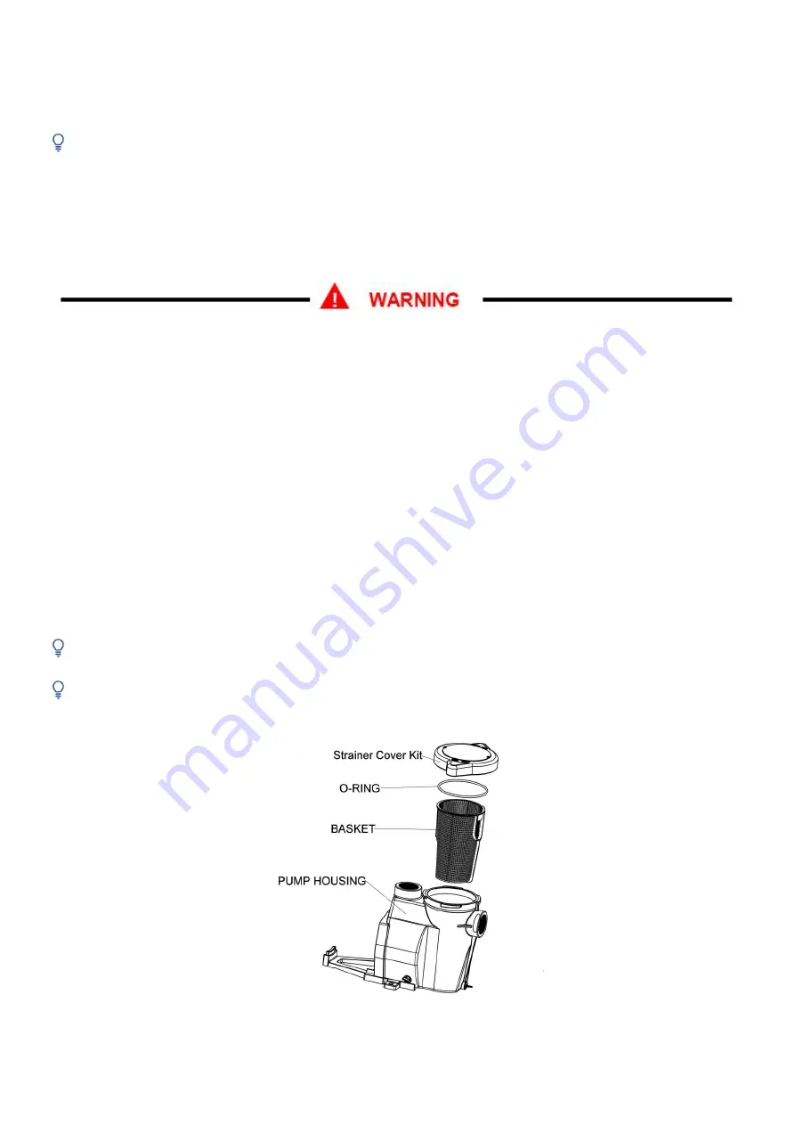
Strainer Pot Assembly

Summary of Contents for PL2516

Page 1: ...1 INSTALLATION AND USER S INSTRUCTIONS VARIABLE SPEED PUMP ...

Page 2: ...ERATING THE PUMP 11 Setting the Clock 11 Using the Default Schedule 12 Custom Schedules and Quick Clean 12 Speed Priorities 14 Operating the Pump While Running 15 MAINTENANCE 15 Pump Strainer Basket 15 Cleaning the Pump Strainer Basket 15 Winterizing 16 SERVICING 17 Electric Motor Care 17 Shaft Seal Replacement 17 Pump Disassembly 18 Pump Reassembly 18 Restart Instructions 19 TROUBLESHOOTING 20 Er...

Page 3: ...his pump To reduce the risk of property damage or injury do not attempt to change the backwash multiport slide or full flow valve position with the pump running RISK OF ELECTRIC SHOCK FIRE PERSONAL INJURY OR DEATH Connect only to a branch circuit that is protected by a ground fault circuit interrupter GFCI Contact a qualified electrician if you cannot verify that the circuit is protected by a GFCI...

Page 4: ... STRONG THAT IT CAN TRAP ADULTS OR CHILDREN UNDER WATER IF THEY COME IN CLOSE PROXIMITY TO A DRAIN OR A LOOSE OR BROKEN DRAIN COVER OR GRATE THE USE OF UNAPPROVED COVERS OR ALLOWING USE OF THE POOL OR SPA WHEN COVERS ARE MISSING CRACKED OR BROKEN CAN RESULT IN BODY OR LIMB ENTRAPMENT HAIR ENTANGLEMENT BODY ENTRAPMENT EVISCERATION AND OR DEATH The suction at a drain or outlet can cause Hair Entangl...

Page 5: ...tem during the filling process This air will compress when the system is pressurized Should the system fail this trapped air can propel debris at a high speed and cause injury Every effort to remove trapped air must be taken including opening the bleed valve on the filter and loosening the pump basket lid while filling the pump SAVE THESE INSTRUCTIONS ...

Page 6: ...2 for simple replacement Strainer cover kit for easy cleaning and maintenance Super duty totally enclosed fan cooled TEFC motor for long life Integral volute and pot reduce hydraulic noise See through lid permits easy inspection of strainer basket Self priming for quick easy start up ETLUS CETL Listed Controller Features Simple user interface IPX6 certified UV and rain proof enclosure Onboard time...

Page 7: ...voltage range of 230 Vrms at either 50 or 60Hz input frequency Program customization may require some trial and error to determine the most satisfactory settings as dictated by the conditions In most cases setting the pump at the lowest speed for the longest duration is the best strategy to minimize energy consumption However conditions may require running the pump at a higher speed for some durat...

Page 8: ...to the pump settings The arrow increases the value of a given setting while decreases the value of a given setting Pressing and holding down either arrow button will increase or decrease the incremental changes faster INSTALLATION Location NOTICE Do not install this pump within an outer enclosure or beneath the skirt of a hot tub or spa unless marked accordingly NOTICE Ensure that the pump is mech...

Page 9: ...inch pipe requires a 12 5 inch 31 8 cm straight run in front of the suction inlet of the pump This will help the pump prime faster and last longer NOTICE DO NOT install 90 elbows directly into the pump inlet or outlet Fittings and Valves 1 Do not install 90 elbows directly into pump inlet 2 Flooded suction systems should have gate valves installed on suction and discharge pipes for maintenance how...

Page 10: ...nded wire There are also fast on type quick connectors however check the local electrical codes for the desired connection method The connections must be permanently made to the grounding terminal see Figure 3 in the field wiring compartment according to the local electrical code The drive will operate on 2 phase Line Line Ground electrical systems as well as Line Neutral Ground systems This pump ...

Page 11: ...you may press and together for 3 seconds to begin again The time LED light will begin blinking Quickly press the Display button within 5 seconds to enter the clock setup mode 2 Use the arrows to choose between a 12 or 24 hour time format 3 Use the and buttons to change the displayed time to the correct time of day In the 12 hour time format AM PM will display in the bottom left corner 4 To exit th...

Page 12: ...ariable Speed Pump the pump must be stopped Be sure that the Start Stop button LED is not illuminated Programming a Custom Schedule NOTICE When programming the LED light next to the parameter Speed Time and Duration you are setting will blink 1 Stop the pump if it is running by pressing the Start Stop button 2 Press the 1 button The LED above the selected SPEED will begin to blink and the Speed pa...

Page 13: ...meter LED will begin to blink See Figure 8 Figure 8 Setting Start Time 5 Use the and arrows to adjust the daily start time for SPEED 1 6 Press the 1 button again and the display will change to SPEED 1 duration The Duration parameter LED will begin to blink See Figure 9 Figure 9 Setting Duration 7 Use the and arrows to adjust the duration for SPEED 1 in hours and minutes NOTICE The duration paramet...

Page 14: ...mp is now on and will run the custom user programmed schedule NOTICE If the pump has been stopped via the Start Stop button the pump will not run until the pump is turned back on by the Start Stop button If the Start Stop LED is illuminated then the pump is on and will run the programmed schedule Speed Priorities For schedule duration settings SPEEDS are prioritized as follows SPEED 1 SPEED 2 SPEE...

Page 15: ...er in the strainer pot Pumps operated in these circumstances may experience a build up of vapor pressure and may contain scalding hot water Opening the pump may cause serious personal injury In order to avoid the possibility of personal injury make sure the suction and discharge valves are open and strainer pot temperature is cool to touch then open with extreme caution To prevent damage to the pu...

Page 16: ...ced air can enter the system and become pressurized Pressurized air can cause the lid to separate which can result in serious injury death or property damage To avoid this potential hazard follow above instructions Winterizing You are responsible for determining when freezing conditions may occur If freezing conditions are expected take the following steps to reduce the risk of freeze damage Freez...

Page 17: ...Motor Care Protect from heat 1 Shade the motor from the sun 2 Any enclosure must be well ventilated to prevent overheating 3 Provide ample cross ventilation Protect against dirt 1 Protect from any foreign matter 2 Do not store or spill chemicals on or near the motor 3 Avoid sweeping or stirring up dust near the motor while it is operating 4 If a motor has been damaged by dirt it may void the motor...

Page 18: ...ace the seal plate face down on a flat surface and tap out the ceramic seal 7 Remove the graphite seal ring on the impeller shaft 8 Clean the seal plate seal housing and the impeller shaft DO NOT run the pump dry If the pump is run dry the mechanical seal will be damaged and the pump will start leaking If this occurs the damaged seal must be replaced ALWAYS maintain proper water level If the water...

Page 19: ...structions If Variable Speed Pump is installed below the water level of the pool close return and suction lines prior to opening hair and lint pot on pump Make sure to re open valves prior to operating Priming the Pump The pump strainer pot must be filled with water before the pump is initially started Follow these steps to prime the pump 1 Remove the pump lid plastic clamp Remove the pump lid 2 F...

Page 20: ...or leaks in suction line Clogged impeller Pump strainer clogged Check suction piping and valve glands on any suction gate valves Secure lid on pump strainer pot and be sure lid gasket is in place Check water level to be sure skimmer is not drawing air Turn off electrical power to the pump Disassemble see page 14 Pump Disassembly Clean debris from impeller If debris cannot be removed complete the f...

Page 21: ...rrent E 14 Module overheating E 04 Constant speed over current E 16 Communication fault E 05 Acceleration over voltage E 17 Current detection fault E 06 Deceleration over voltage E 24 Inverter hardware fault E 07 Constant speed over voltage E 08 Under voltage fault E 09 Motor overload E 10 Inverter overload E 16 Communication Link between the HMI and Motor control has been lost Check the jacketed ...

Page 22: ... 01 000020 003 Motor Drive PL2516 1 12d 9 01 000020 004 Motor Drive PL2519 1 13b 9 01 001500 001 Motor M15CU 1 13c 9 01 001800 001 Motor M18CU 1 13d 9 01 002200 001 Motor M22CU 1 1 1 1 4b 9 01 020000 001 Strainer Housing for PL2517 PL2518 PL2516 PL2519 1 Seal Plate 9 9 01 010000 006 10 9 01 010000 007 11 9 01 010000 008 Mounting Foot Supporting Foot Drain Plug with O ring 2pcs 15 9 01 010000 017 S...

Page 23: ...ut Current 5 5A Input Frequency Single phase 50 or 60 Hz Maximum Continuous Load 1 5HP Speed Range 450 3450 RPM Environmental Rating NEMA Type 3 Pump Dimensions Pump Performance Curves PL2515 Model PL2515 Port Size 1 5 x1 5 Model Specifcationes ...

Page 24: ... 230 V Input Current 5 5A Input Frequency Single phase 50 or 60 Hz Maximum Continuous Load 1HP Speed Range 450 3450 RPM Environmental Rating NEMA Type 3 PL2517 PL2518 PL2516 PL2519 Model PL2517 PL2518 PL2516 PL2519 7A 1 5HP 8A 2HP 10A 3HP Port Size 2 x2 Model Specifcationes ...

Page 25: ...f two 2 years following the date of purchase This limited warranty does not cover failures due to abuse accidental damage or when repairs have been made or attempted by anyone other Legal Disclaimer Inyo Holdings LLC is owned and with legitimate use by Inyo Holdings LLC Any other company name brand product name trademarks or product model numbers referenced in this manual are owned by respective t...

Reviews: