48
5. Drain the oil fill of oil-lubricated bearings. ( Section 7.2.3.1.4 Page 45)
7.4.3 Dismantling the motor
1. Disconnect the motor from the power supply.
2. Unbolt the motor from the baseplate.
3. Shift the motor to separate it from the pump.
1. If required, suspend or support bearing bracket 330 to prevent it from tipping over.
2. Unbolt support foot 183 from the baseplate.
3. Undo hexagon nut 920.01 at the volute casing.
4. Pull the back pull-out unit out of the volute casing.
5. Remove and dispose of joint ring 411.
6. Place the back pull-out unit on a clean and level surface.
7.4.5 Removing the impeller
The notes and steps stated in ( Section 7.4.1 Page 47) to ( Section 7.4.4 Page 48) have
been observed/carried out.
The back pull-out unit is kept in a clean and level assembly area.
1. Undo impeller nut 922 (right-hand thread).
2. Remove impeller 230 with an impeller removal device.
3. Place impeller 230 on a clean and level surface.
4. Remove keys 940.1 from shaft 210.
5. Remove and dispose of joint rings 411.
7.4.6 Dismantling the shaft seal
7.4.6.1 Dismantling the mechanical seal - cylindrical casing cover
The notes and steps stated in ( Section 7.4.1 Page 47) to ( Section 7.4.5 Page 48)
have been observed/carried out.
The back pull-out unit is kept in a clean and level assembly area.
7.4.4 Removing the back pull-out unit
Pumps without spacer-type coupling: the motor has been removed.
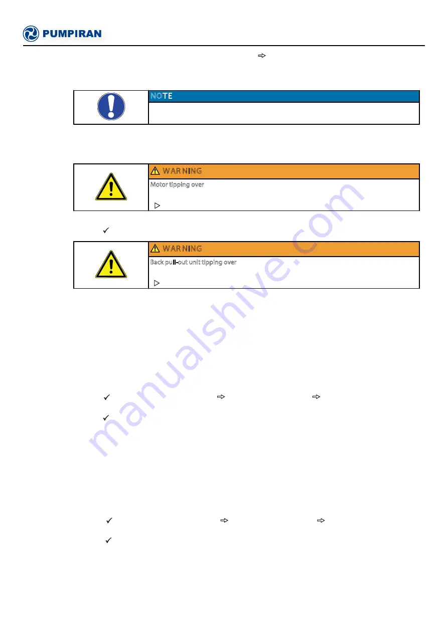
NOTE
For pump sets with spacer-type couplings, the back pull-out unit can be removed while
the motor remains bolted to the baseplate.
WAR NING
Motor tipping over
Risk of squashing hands and feet!
Suspend or support the motor to prevent it from tipping over.
WAR NING
Back pull-out unit tipping over
Risk of squashing hands and feet!
Suspend or support the bearing bracket at the pump end.
7 Servicing/Maintenance


