www.pulsar.pl
BNC04124B
G
REEN POWER CCTV BNC
7
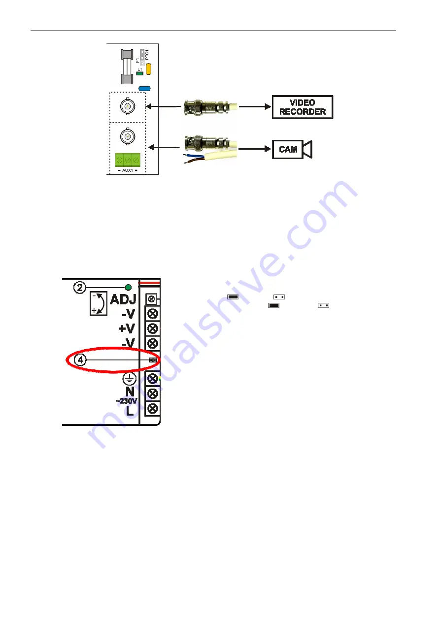
- connect the video signals from the cameras and the DVR to the BNC sockets
Figure 4. Connecting the camera and DVR to the BNC module.
5. Use the F1/PTC1 ÷ F4/PTC4 jumpers to select the type of short circuit / overload protection of individual circuits.
Jumper in the Fx position – melting fuse activation, PTCx – PTC fuse activation.
6. If needed, the following technical connections can be made:
- FPS technical output of the PSU status – indicates the voltage loss at any of the outputs (AUX1 ÷ AUX4).
- TAMPER indicating enclosure opening.
7. Check the power supply output voltage:
- output voltage of the unloaded power supply without a battery should amount to U=13,8V DC.
8. Set the battery charging current using the jumper (component 4, Figure 5):
Figure 5. Selection jumper for charging current.
Selection jumper for charging current:
Ibat =1 A
Ibat =2 A
Description:
jumper on,
jumper off.
Factory setting: Ibat =1A (jumper on).
9. Connect the battery according to the color markings:
- battery output (+V): BAT+ cable / red
- battery output (0V): BAT- cable/ black
10. Check the optical indication of the PSU status: green LED light on the BNC module.
11. Close the cover after installing and checking the operation of the power supply.
3. Power supply operation indication.
3.1. Optical indication.
The PSU has 11 LED lights at the front panel:


