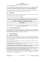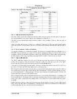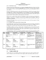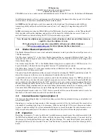
PS Engineering
PMA8000 Audio Selector Panel and Intercom System
Installation and Operator’s Manual
200-890-0000
Appendix D
Revision 9, June 2005
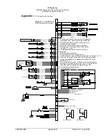
Appendix
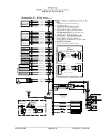
D, J2 Connector Interconnect
35
36
24
23
25
Pass. Mic Lo
Pass. Mic Hi
37
38
Pass. Mic Lo
Pass. Mic Hi
39
40
Pass. Mic Lo
Pass. Mic Hi
41
42
Pass. Mic Lo
Pass. Mic Hi
Copilot Mic Audio
Copilot PTT
Copilot Mic Lo
Copilot Mic Jack
Ent. #2 Mute
PMA8000 J2 CONNECTOR
(Sub-D 44-pin male on tray)
Ent. #2 Input
27
26
28
Ent. #2 Audio (R)
Ent. #2 Audio (L)
Ent. #2 Audio Lo
Notes:
Ent. #1 Audio (R)
Ent. #1 Audio (L)
Ent. #1 Audio Lo
Ent. #1 Input
5
6
7
Ground Lug
See Note 4
PA Mute
18
29
30
IR Data Out
Remote Enable
24
23
25
27
26
28
Speaker Hi
Speaker Lo
44
43
1. All Power, and Ground wires must be #18 gage wire
Lighting #22 AWG, other wires minimum #24 AWG.
2. All shields should be grounded at audio panel only,
other end remains floating
3. Pins 8 and 9 connected through a 5 A breaker.
4. PA Mute is a TTL level logic output that is pulled
low when PTT active.
5. All shielded wires must be MIL 22750 or 27500.
6. Reserved
7. Music inputs are independent.
Connect together to use a single source
for both inputs. For music distribution information, see Section 2.4.14.1.
8. When pin 19 is switched to ground, the PA mode is activated,
placing pilot microphone on speaker output when PTT active.
See Sect 2.5.13.
9. AUX enable goes low when AUX button is on. May be used for
passenger mute inhibit by connection to pin 13. Should NOT be
used when DME is installed and played through AUX
10. Connections for Future System
11. No connection to Pin 17
Unswitched Input #4 Hi
Unswitched Audio Lo
Unswitched Audio #4
15
See Note 9
7
6
5
28 V Lights Hi
28-Volt lights lo
7
6
5
14 V Lights Hi
14-Volt lights lo
AUX Enable
See Note 10
See Note 9


