


3
TABLE OF AVAILABLE PARAMETERS:
Shceme participation:
Name
Range
З
ащ
и
та
с
П
ар
о
л
а
Parameter description
0 1 2 3 4 5 6 7
1
Clock
h:m:s
Clock
* * * * * * *
2
ОN
24h/15min
Beginning of time zone (El. Heater)
* * * * * * *
3
Off
24h/15min
End of time zone (El. Heater)
* * * * * * *
4
GoodTnk
min÷max
Comfort t
°°°°
C
in main tank
* * * * * * * *
5
dT1-Sol
3÷35°C
*
Temperature difference – solar/ tank
* * * * * * *
5а
dT1-hst
2 or 5°C
*
Hysteresis of dT1-Sol
* * * * * * *
6
dT2-Kot
3÷15°C
*
Temperature difference supplementary heater / tank
* * *
6а
dT2-hst
2 or 5°C
*
Hysteresis of dT2-Kot
* * *
7
MinTank
5÷75°C
*
Minimal tank t
°°°°
C
maintained by El. heater
* * * * * * *
8
CH Pump
5÷75°C
*
Suplimentary source t
°°°°
C
to start CH pump
*
9
MaxTank
10÷95°C
*
Maximal t
°°°°
C
in tank
* * * * * * * *
10
Min Sol
5÷80°C
*
Temperature in solar source to enable solar pump
* * * * * *
10а
Min Sol
-hst
2 or 5°C
*
Hysteresis of Min Sol
* * * * * *
11
DefrSol
-40÷10°C
*
Defrost t
°°°°
C
of solar (to starts solar pump)
* * * * * *
12
MinKot
5÷90°C
*
Minimal t
°°°°
C
of supplementary heating to enable
DHW valve/pump
* * *
13
TankA/B
5÷90°C
*
Tank switching t
°°°°
C
Main/Storage or (coil 1 / 2)
*
14
PumpSec
2÷128sec
*
Pump operation hold time
* * * * * *
15
Act Sol
0÷240min
*
Delay of electric heater activation
* * * * *
16
AutCool
Y / N
*
Automatic cooling of tank to „GoodTnk” t
°°°°
c
* * * * * *
17
Passwrd
Password for majour parameter access
* * * * * * * *
18
Schm
0 ÷ 5
*
Application select scheme
0 1 2 3 4 5 6 7
19
Lt./Min
0.0÷5.0
*
Expected flow of solar pump
(for statistics purpouse)
* * * * * *
20
dTLoss
0÷10°C
*
Expected t
°°°°
C
losses of trace
(for statistics purpouse)
* * * * * *
21
Pump%Lo
25÷100%
*
Minimal opperation speed of HF pump
* * * * * * *
22
PumpºcdT
0÷25°C
*
Sets upper t
°°°°
C
margine obove dT1-Sol for HF
pump to operate at 100% (speed vs t
°°°°
c
distributuion)
* * * * * * *
23
SolOvrh
N
*
Solar panel overheating counter
- can be cleared
* * * * * * *
24
TnkOvrh
N
*
Tank overheating counter
- can be cleared
* * * * * * * *
25
AutoVac
Y / N
*
Automatic activation of “Vacancy” mode
* * * * * * * *
26
LimTnkА
Y / N
Limiting of Main tank t
°°°°
C
to “GoodTnk”, excess
energy is transferred to storage tank
*
MEANS FOR PREVENTION AND PROTECTION:
Type
Action
1
Anti frost of Solar
Forced circulation of solar pump
2
Overheat of solar
Forced circulation of solar pump
3
Thermal shock of solar
“Slow” solar pump activation
4
Thermal shock of pipeline
“Slow” solar pump activation
5
Anti frost of pipeline
Trace heating/ Forced circulation of solar pump
6
Tank overheat
“Vacancy” mode
Operation with “maximal thermal losses”
Auto cooling to “TBGood”
*Heat transfer to supplementary heating system
*Activation of emergency drainig valve
7
Pumps blockage
Forced activation on certain period of inactivity
8
Current time lost (time not being set after power
failure with longer duration)
Blinking display
* Available only for certain operational schemes
4
OTHERS:
„
Vacancy
” mode - forced cooling of tank (during night time) to have full heat storage for next day.
Selectable hysteresis 2 or 5 ºC
Fault notification - entire screen blinking
Displays sensor failure message: „no” – no sensor; “sc” – sensor short circuited
Displays state of R1, R2 and R3
Manual activation/test of pumps
Important parameter change is password protected
Automatical switching to “Vacancy” mode if unit is left unattended and possible tank overheating is sensed
PWM output for HF pump speed control ; PWM – 1kHz
TECHNICAL DATA
Power supply: 230V±10% /50Hz. ≤ 2VА
Instalation on DIN rail 35mm; to be incorporated
Enviroment: -5T45, RH80%
Storage and transportation-20/+60 º C
Overall dimentions 68x85x58 mm.
Protection casing IP20
Sensors: durability 200 ºC
Measurment and display: -40ºC÷150 ºC;
Accuracy ±1ºC in range (-5ºC ÷ +100 ºC);
±4ºC not in range
Outputs:
-Relay R1(SPST)- 230V - 5A or 180W/AC3 (motor)
-Relay R2(SPDT)- 230V -16А or 1500W/AC3 (motor)
-Relay R3(SPDT)- 230V - 5A or 180W/AC3 (motor)
Real time clock authonomy up to 2h
MAIN CHARACTERISTICS
:
1.
Supplies directly power for electrical heater (up to3kW) and two circulation pumps / trace heater or
directional valve.
2.
Reads three temperatures.
3.
Build in conductivity sensor - terminals 3 and 4 – (TS3 not used) for water level monitor and filling
4.
Fully programmable by 29 parameters
5.
F
ast and direct selection of heater operation mode by separate button among „Auto” /On./ Off./Vacancy
6.
Build in real time clock with programmable time zone for additional electric heater activation.
7.
Relay outputs 3 (separate) for:
-
R1 n.o. SPST, supplies phase for pump/trace heating (HFпомпа)
-
R2 n.o./n.c SPDT, voltage free contact for electric heater
-
R3 n.o./n.c SPDT, supplies phase for pump/direction valves
8.
Backup power supply for real time clock
9.
Alphanumeric LCD display 8х2 rows.
10.
Navigation – 3 push buttons. One button for elecric heater activation
11.
Statistics (solar energy accumulated, alarm events)
12.
Diagnostic information for sensor failure.
13.
A set of functional means for independatnt action at critical events.
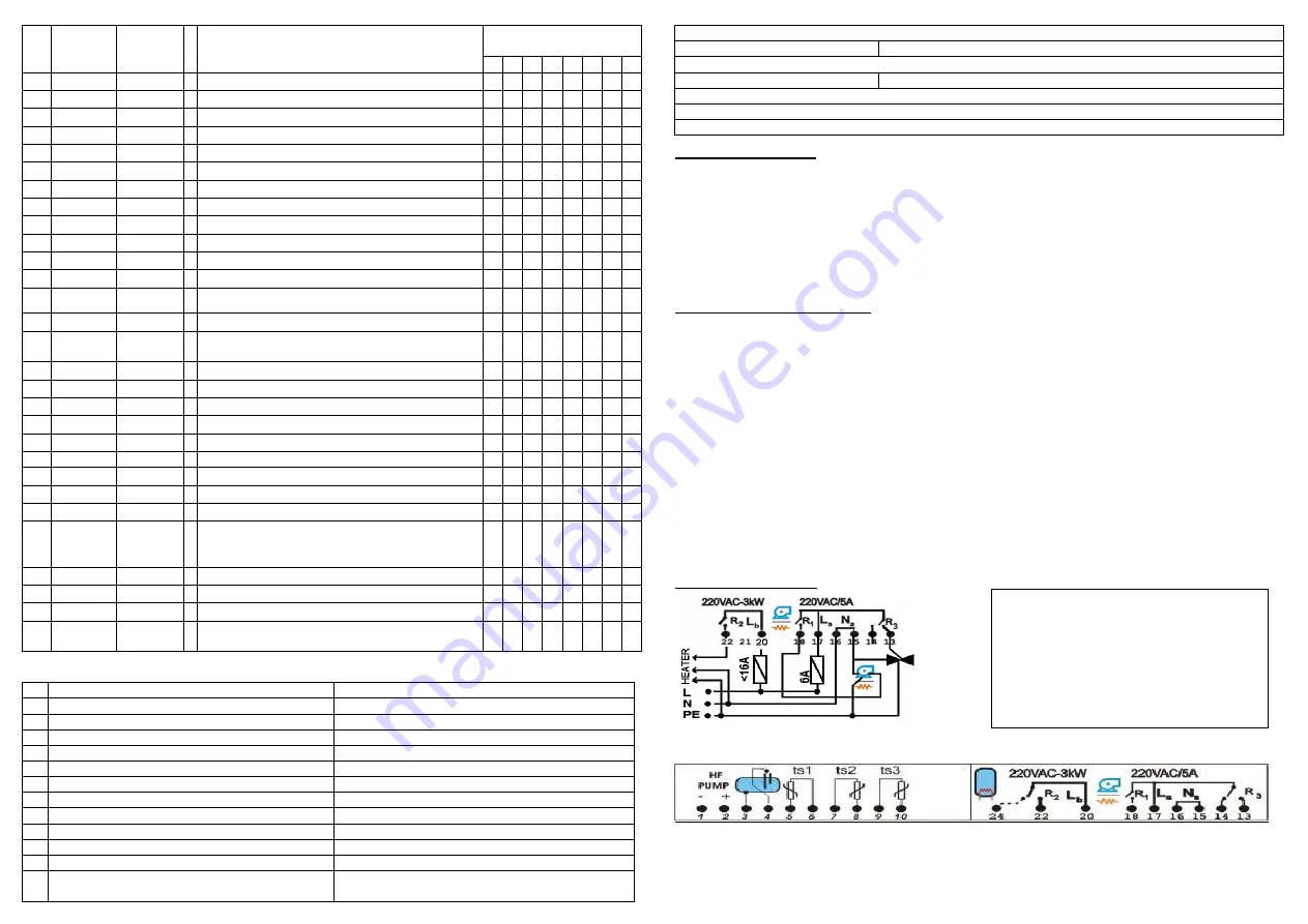
WIRING DIAGRAM
Attention!:
Junction for heater’s neutral “N” should be made on external terminal block
(not provided)!
All conections to PE should be made to external terminal block
(not provided)
!
-
Power supply 230V AC
– (internal and R1) – #17 (Live “La”); #16 („N”);
-
R1: Pump/trace heating
– #18 (switches Live); #15 („N”); – 5А max.
-
R2: Electric heater
– #20 (separate Live ”Lb”); #22 output – 16А max.
-
R3: Pump2/Valve(Open/Close) – (switches Live) #13 (n.o); #14 (n.c. ) – 5А max.
Terminals 3 and 4 – level sensor input (measures conductivity of water)
Terminals 1 and 2 – PWM output for HF pumps
Attention!
Power supply should be applied via fuses:
-
La – Circuit Breaker max 6А for trm. 17
-
Lb - Circuit Breaker max 20А for trm. 20
-
If UPS is used, tem. 17/16 should be
supplied by UPS while trm.20 and heater
“N” should be connected before UPS
(directly to mains).


