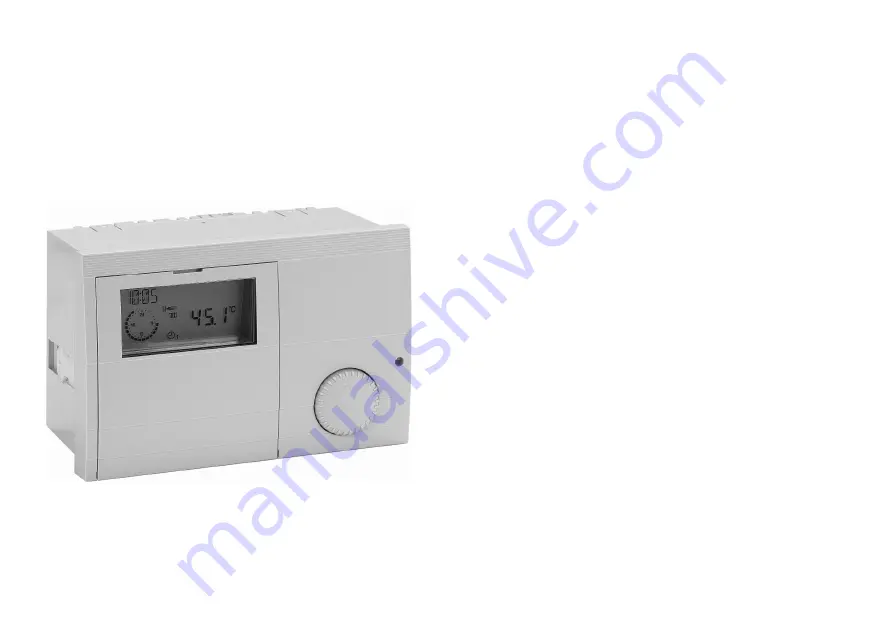
E8.4401
System Manager
Operating instructions
Please observe the safety instructions and read through this manual carefully before commissioning the equipment.
Page 1: ...E8 4401 System Manager Operating instructions Please observe the safety instructions and read through this manual carefully before commissioning the equipment...
Page 2: ...warranty null and void Important text passages Important notes are denoted by an exclamation mark E This attention symbol is used to point out dangers in this manual Description Declaration of conform...
Page 3: ...Users 11 Time programs 11 Expert 11 Levels 11 Installation 11 Hot water 11 Heating circuit I II 11 Part 2 Overview of display values and settings 12 General area 12 Date Time Holiday 12 Service 14 Cod...
Page 4: ...x header temperature 30 MIN T COLL min header temperature 30 HYST BOILER dyn switching hysteresis stage 1 31 with HYST TIME Hysteresis time 31 CAP MODULE boiler output for each stage 32 MIN MOD CASC m...
Page 5: ...o heating requirement 43 Switched according to heating limits 43 Delayed pump switch off 43 Pump blocking protection 43 Mixer motor blocking protection 43 Part 4 Installation and Start up 44 Installat...
Page 6: ...f the display It takes effect when the setting is not changed for 5 s The following operating modes are available for selection i Standby OFF Heating OFF and hot water preparation OFF only frost prote...
Page 7: ...operating mode The operating mode set here affects the boiler regulation and the integrated heating circuits of the controller Each heating circuit can be assigned a separate operating mode from the...
Page 8: ...urrent time B Freely selectable display refer to DISPLAY SEL parameter C DCF reception OK only with receiver connected D Bus symbol when this symbol does not appear check the data line to the CAN cont...
Page 9: ...the controller Operating elements A Shaft encoder Search for value level or adjust value B Programming key Select a value level Select a value level to change Save a new value C Change display LED ON...
Page 10: ...a The current area DISPLAY appears in the display for a short time 1 clock circuit After the clock circuit the display switches to the current operating level INSTALLATION This is displayed for a shor...
Page 11: ...d to make settings installation technician E Values in the expert level are protected by a code no damage malfunction possible Levels The settings in the different areas are sorted into operating leve...
Page 12: ...sted TIME Hours Current hours blink and can be adjusted seconds are set to 00 when stored YEAR Adjust current year MONTH Adjust current month DAY Adjust current day date If a heating system controller...
Page 13: ...rms the time change on the Sunday following this date at 2 00 am or 3 00 am If no time change is required please set MONTH STOP to the same value as MONTH START and DAY STOP to the same value as DAY S...
Page 14: ...Pump heating circuit 1 header pump 02 A2 Pump heating circuit 2 03 A3 Hot water charging pump 04 A4 Mixer OPEN heating circuit 2 05 A5 Mixer CLOSED heating circuit 2 06 A6 HS1 ON 07 A7 HS2 ON 08 A8 H...
Page 15: ...SIDE Outside temperature T COLLECTOR Boiler temperature T DHW Hot water temperature T ROOM D 1 Room temperature heating circuit 1 only with remote control T FLOW D 2 Flow temperature heating circuit 2...
Page 16: ...T PRG 00 Load time program factory settings RETURN Exit level using SW NO XXX XX Display software number with index please specify if you experience problems or have questions about the controller CA...
Page 17: ...or operating hours Delete active maintenance display Open control panel cover press prog button set repeat value to 00 using and confirm with Delete programmed annual message In the General Service l...
Page 18: ...IDE Outside temperature T COLL DES HS Header set value cascade T COLLECTOR HS Header temperature cascade RETURN Exit level using T OUTSIDE The measured outside temperature is smoothed for control purp...
Page 19: ...ious time required to heat up with heat up optimisation activated RETURN Exit level using Display only appears if the sensor is connected and the value is present in the system If the set value is not...
Page 20: ...cuit 01 Heating circuit 02 01 RETURN Exit level using IV Internal Values Space for entering the parameters stored in the system GERMAN Language Select controller language CONTRAST Adjust intensity of...
Page 21: ...your own hot water short time heating function using the third hot water enable facility 1X DHW 1x Hot water 01 The storage tank is enabled for charging e g for showering outside hot water times Char...
Page 22: ...d in first enable time T ROOM DES 2 used in second enable time T ROOM DES 3 used in third enable time of active heating program for this heating circuit T REDUCED Required room temperature setting dur...
Page 23: ...chapter entitled Circulation pump control HEATSLOPE The gradient of the heat slope indicates by how many degrees the flow temperature changes if the outside temperature rises or drops by 1 K Setting t...
Page 24: ...ar in the display until the function is carried out successfully the next day or is ended e g by adjusting the operating mode switch During the adaptation the water heating and the heating optimisatio...
Page 25: ...ected room sensor operating mode selection Warm up optimisation occurs only if the reduced time of the heating circuit is at least 6 hours MAX OPT TIME maximum bringing forward Only active with OPTIM...
Page 26: ...rcuit HTG PROG 2 D 1 2nd heating program for first controller heating circuit HTG PROG 1 D 2 1st heating program for second controller heating circuit HTG PROG 2 D 2 2nd heating program for second con...
Page 27: ...day Sunday MO SU Monday Sunday Open weekday block see left I ON 20 C First switch on time set value I 20 C Set first switch on time for example 6 00 hrs Confirm first switch on time I OFF 20 C First s...
Page 28: ...ting Mo to Fr 06 00 to 08 00 16 00 to 22 00 Sa and So 07 00 to 23 00 Heating time 1 Heating time 2 Heating time 3 Mo Tu We Th Fr Sa Su Heat circuit 2 Heating program 1 factory setting Mo to Fr 06 00 t...
Page 29: ...2 Overview of display values and settings Timer Program Area 29 Hot water Factory setting Mo to Fr 05 00 to 21 00 Sa and So 06 00 to 22 00 Heating time 1 Heating time 2 Heating time 3 Mo Tu We Th Fr S...
Page 30: ...ing circuits are sequentially numbered starting with 01 Heat circuit numbers must not be assigned twice For replacement controllers however please enter exactly the same heating circuit numbers as the...
Page 31: ...ng heat generator loads The effective switching hysteresis is reduced linearly after the burner is switched on from the set HYST BOILER to the minimum hysteresis 5K during the hysteresis time HYST TIM...
Page 32: ...ction with Prog button Input Adjustment of HG output Stage HS not available or not active In the case of heat generators of equal capacity release of a HS is sufficient e g or 2 stage WE 1 01 01 WE 1...
Page 33: ...hed off BLOCK TIME currently remaining value Display of current delay time Only if delay 0 is it possible to operate the next heat generator T BOIL MAX maximum temperature of the heat generator Protec...
Page 34: ...is always switched after the first stage SEQ MODE sequence change mode 01 Only heat generator sequence 1 02 Only heat generator sequence 2 03 Change between sequence 1 and 2 according to operating hou...
Page 35: ...en cancelled terminated the controller continues heating using the set operating mode If no heating is required set the operating mode to i Standby OFF Screed program SCREED activation of screed dryin...
Page 36: ...cuits are blocked during hot water preparation The mixers close and the heating circuit pumps switch off The mixer circuits are enabled again when the HS has reached the temperature of hot water tempe...
Page 37: ...ter the burner has switched off If heat is requested by a heating circuit the run down is cancelled The charge pump blocking kicks in and can also cause the run down function to be cancelled greater t...
Page 38: ...w temperature for the swimming pool heat exchanger The swimming pool water temperature sensor is connected to the room sensor connection for the heating circuit see FBR Plug III 1 2 The flow temperatu...
Page 39: ...The heating circuit is switched off Switch on with 1K hysteresis This adjustment concerns the weather dependent shut down If room temperature regulation is enabled ROOMS INFL 0 the thermostat function...
Page 40: ...is limited to the maximum flow temperature setting overheating protection E The pump of the direct heating circuit is not switched off until the HS temperature exceeds the set maximum flow temperatur...
Page 41: ...eneral function description Heat circuit control Weather dependent control The HS or flow temperature is determined via the set heat slope to suit the measured outside temperature in such a way that t...
Page 42: ...on temperature setting HS frost protection header frost protection Header frost protection is activated when the header temperature drops below 5 C The cascade is switched on until the header temperat...
Page 43: ...ulated by the controller exceeds the heating limit specified here heating is disabled the pumps switch off and the mixers are closed The heating is enabled again when the outside temperature drops bel...
Page 44: ...he control panel at the left and right hand side of the unit a Pull the mounting clamp at the low away from the controller wall toothing b In this condition slide the mounting clamp down or up until t...
Page 45: ...be laid separately away from mains cables After connecting or modifying the connections of sensors and remote controls the controller must be briefly switched off mains switch fuse The function of the...
Page 46: ...Installation Part 4 Installation and Start up 46 2 2 B 2xBM r r r r D D v 2 3 4 D System diagram with direct heating circuit...
Page 47: ...Part 4 Installation and Start up Installation 47 2 2 B 2xBM D D v r r r r 2 3 4 D System diagram with header pump...
Page 48: ...switch heating circuit 2 ST9 1 2 Data line CAN bus ST9 3 4 Power supply CAN bus II 1 Neutral conductor mains II 2 Power supply unit II 3 Power supply relay II 4 Pump heating circuit 1 header pump II...
Page 49: ...e description of the overall scope of functions Display of the system parameters Entry of the heating circuit parameters Room temperature control Automatic adaptation of the heat slope Remote control...
Page 50: ...r s clock is updated daily at 3 20 a m and also 5 minutes after switching on the power supply If the time is not automatically corrected from the specified time select a different installation site fo...
Page 51: ...or the remote control FBR see connection diagram are used for installation As soon as a short circuit is detected at terminals 2 and 3 of the corresponding connector the heating circuit assigned switc...
Page 52: ...nsor type is selected in the start up level during start up The start up level is displayed when the operating cover is opened after the supply voltage has been switched on once only It can be reactiv...
Page 53: ...a heated room Approx 2 5 m above ground Not above windows or ventilation shafts Installation Detach the cover Attach the sensor with the supplied screw Boiler sensor KF KFS H Installation location Imm...
Page 54: ...the case of mixer operation v approx 0 5 m behind the circulation pump Installation Thoroughly clean the flow pipe Apply heat conductive paste A Secure sensor with stretch band Storage tank sensor SPF...
Page 55: ...C sensor 01 1kOhm PTC sensor Commissioning procedure 1 Please read this guide carefully before commissioning 2 Fit controller make electrical connections and switch on heat generator and supply voltag...
Page 56: ...r controllers and control units The bus ID 00 15 expert level parameter is used to number the heating circuits in the system Each operating module and each mixer motor module is given the number of th...
Page 57: ...ave already been set RESET Overwrite all settings with default values except language time and sensor values The additional button must be pressed when the controller is switched on mains on until EEP...
Page 58: ...ion to Control unit Room temperature displayed and current room temperature setting blanked out see Display heating circuit In mixer motor expansion controllers with connection to Boiler controller Ou...
Page 59: ...r consumption Max 8 VA Switching capacity of the relays 250 V 2 2 A Maximum current on terminal L1 10 A Enclosure to EN 60529 IP 40 Safety class II to EN 60730 Totally insulated Switch panel installat...
Page 60: ...60 Malfunctions due to improper operation or settings are not covered by the warranty GB 0706 6 6701 961 01 Printed in Germany Subject to modification...