background image

Protean Instrument Corporation 


43 


Program MPC 

900


Count


Routine


Definition


Page


1


Naming


the


Count


Routine


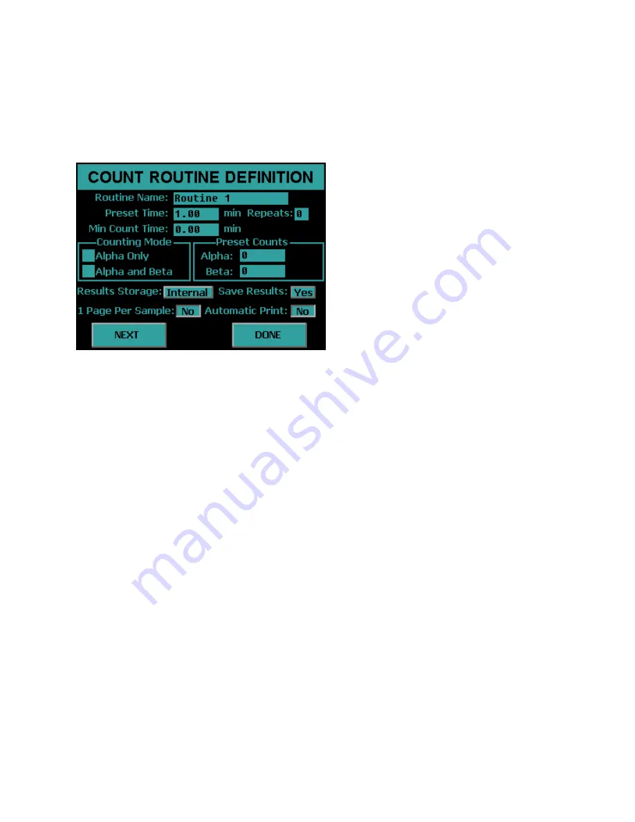
The name which will appear in the menus for the Count, Data, and Calibration functions 
should be defined.  This name will identify to the operator the type of samples to be 
counted using the defined routine.  The name will also appear in the printed report. 
 

Preset


Time


The preset time specifies one of several conditions which can terminate an acquisition.  
This field defines the maximum amount of time for sample analysis.  For most 
applications,  this will be the only preset condition that is used.  Therefore this time 
equates to the amount of time each sample is analyzed.  The length of time is usually 
selected to meet a desired sensitivity or minimum detectable activity requirement.  How 
much time is needed should be determined by the worse case efficiency and 
background values. 
 
The preset time is set by pressing the 

Preset Time

 field and entering the time.  The 

minimum preset time must be greater than 0.01 minute.

Summary of Contents for MPC-900

Page 1: ...Protean Instrument Corporation MPC 900 Gas Flow Detector Revision 1 2 ...

Page 2: ... 15 Print and Save Factory Plateau 17 Setting the Calendar Clock 18 Installations Without Attached Printer 18 Read the Manual 18 MPC 900 Overview 19 Menu Driven Operation 19 Pass Code Protection 19 Count Function 19 Calibration Function 19 Control Charts 19 Program Function 20 Counting Parameters 20 Background Parameters 20 Efficiency Parameters 20 Battery Backup 20 Printer 21 Computer Connectivit...

Page 3: ... 27 Routine Definition Page 3 27 Routine Definition Page 6 28 Step 2 Calibrate 29 Step 3 Count 31 Review 33 Setup Menu 34 Screen Utilities 34 Calibrating the Touch Screen 34 Backlight Brightness 35 Beep Volume 35 Program Menu 36 Import Settings 36 Instrument Parameters 37 Printer 38 Gas Flow Option 39 Set Calendar Clock 40 Setup Pass Codes 41 Set Instrument ID 42 Define Counting Routines 42 Count ...

Page 4: ...6 Count Routine Definition Page 2 47 Count Routine Definition Page 3 52 Count Routine Definition Page 4 53 Count Routine Definition Page 5 54 Count Routine Definition Page 6 55 Calibration Menu 57 Plateau Determination 58 Acquiring a Plateau 59 Viewing a Plateau 60 Manual Background Efficiency Entry 61 Radon Efficiency Factors 63 Import Control Chart Limits 64 Print All Calibration Info 64 Control...

Page 5: ... The Data Display 89 Printer Test 90 Guarding Against Obsolescence 91 Plateau Data CSV File Format 92 Alpha Control Chart Checks Data CSV File Format 93 Beta Control Chart Checks Data CSV File Format 94 Background Control Chart Checks Data CSV File Format 95 Sample Data CSV File Format 96 Trend Data CSV File Format 97 Radon Subtraction 100 Determination of Radon Efficiency Factors 101 Routine Coun...

Page 6: ...PS 108 Removing Low Voltage Power Supply 108 Installing Low Voltage Power Supply 108 Operating Environment 109 General Electrical Failures 109 Blows Main Fuses 109 Failure to Initialize on Power up 110 Intermittent Lockup 110 APA 10 D and HV 20 D Status Indicators 111 Beta Background is High 111 Sample Counts are zero 111 Performance Changes Background 111 Gas Quality 111 Contamination 112 Electro...

Page 7: ...Requirements 120 Low Background Material Selection 120 Background Stability 120 Absolute Counting Efficiency 121 Intrinsic Detector Efficiency 121 Counting Geometry and Efficiency 121 Sample Self Absorption and Counting Efficiency 122 Calibrated Conversion Factors 123 The Control Chart 123 MPC 900 OPTIONS 124 MPC 900 SPARES ACCESSORIES 124 LIMITED WARRANTY 125 ...

Page 8: ...ditional assistance or information contact us at Protean Instrument Corporation 231 Sam Rayburn Parkway Lenoir City TN 37771 Phone 865 717 3456 FAX 865 717 3456 www proteaninstrument com WARNING The power plug for this instrument shall only be inserted in a socket outlet provided with a protective earth contact Any interruption of the protective conductor inside or outside the instrument is likely...

Page 9: ...ng power and pressing buttons there are a few preliminary details to consider The instructions that follow assume that the instrument is positioned in its permanent location in preparation for usage Allow about six inches in the rear of the instrument for access for peripheral cables Visual Inspection Visually inspect the instrument for any obvious damage If everything looks in order proceed with ...

Page 10: ... power cord to the IEC power entry module on the bottom left of the rear of the instrument Plug the power cord into the power mains and switch on the power The power switch is also located in the power entry module above the cord The display should then show the Top Menu screen seen below ...

Page 11: ... is 10 PSI Connect the instrument to your manifold using the transparent gas line and quick disconnect fittings included with the tank regulator o A new tank of gas is generally pressurized to around 2400 PSI Do not open the tank valve until the regulator is installed o Securely install the regulator on the gas cylinder Note Counter Clockwise to tighten o Close the regulator valve fully clockwise ...

Page 12: ...nd language We do not maintain detailed instructions for all printer models and brands The printer connection is a standard USB interface Connect the printer USB cable to the back of the MPC 900 USB port Select the correct print driver The goal is to test the printer in order to do so the correct printer driver must be selected Press the Setup button on the Top Menu screen The Setup Menu will be d...

Page 13: ...splay the menu seen below Press the Printer button to display the Printer Option Menu below If connecting a line printer toggle the button to show 9P ESC P otherwise choose PCL5 for a printer using the PCL5 printer command language Press OK to accept the changes Press EXIT until the Top Menu is displayed ...

Page 14: ...t button The printer should begin to print out a test page similar to the one shown below If the printed test page appears normal then continue to the next phase of the installation If the test page does not print correctly verify that the correct print driver is selected and that the printer cable connections are secure ...

Page 15: ...planchet and carrier insert that holds the source as close to the top surface of the carrier as possible The source planchet must not protrude above the plane of the top surface of the carrier Press the Diagnostics button on the Top Menu Press the Manual Count Button Refer to the Diagnostics section of this manual for a detailed account of the Manual Count routine Select Alpha and Beta counting mo...

Page 16: ...hese instruments are Am 241 Th 230 Po 210 C 14 Tc 99 Cs 137 and Co 60 The first three listed are primarily alpha emitters Most alpha emitters also decay with some percentage of betas and x rays which will show in the beta channel of the display Put a clean blank planchet into the magazine and count for 10 minutes Typical results for a 10 minute count at elevations of sea level to 1000 ft are Alpha...

Page 17: ...lable for your inspection It is recommended that you print the plateau graph and data and maintain this document for future reference Proceed as follows From the Top Menu press the Setup button Press the Calibration button Press Plateau Determination Press the PRINT button to print the plateau The plateau can be viewed on the console screen by pressing the VIEW button From the Plateau Data View sc...

Page 18: ...ed in previous tests cannot be printed In such installations save the plateau to the USB flash drive and copy the PLATEAU CSV file from the USB flash drive to a safe location Refer to the Export Data section Read the Manual The installation of the MPC 900 is now complete The user should now have some feel for how to interact with the instrument Only a few of the many and powerful functions have be...

Page 19: ...ntered Count Function Routine Sample counting begins by pressing the Single Count or Batch Count button from the Top Menu Calibration Function Calibration of the MPC 900 consists of setting the detector operating voltages and determining efficiency and background values for the count routines In most cases control charts are also used to monitor instrument stability Each counting routine uses sepa...

Page 20: ...inimum time alpha counts and beta counts Count mode is either alpha and beta or alpha only In the alpha and beta mode the alpha and beta counts are separated by a pulse height discriminator in a single preset time interval In the alpha only mode the sample detector is operated at the alpha plateau voltage where the detector is insensitive to betas Background Parameters Background values can be sel...

Page 21: ...ilable to copy saved data resident on the instrument to a USB flash drive in CSV comma separated value format The CSV output formats are described in detail in this manual International Power Entry The rear panel power entry module supports a universal IEC line cord attachment The power entry module can be converted for operation at either 110VAC or 220VAC 50 60Hz Limited Warranty A twelve month l...

Page 22: ...should be used to achieve the highest counting efficiency Since radiation from the sample follows the inverse square law a very small change in distance from the detector has a very large effect on the intensity of the radiation seen by the detector The limiting factor for close sample spacing is the thickness and uneven nature of the sample itself Smear or swipe samples are often very wavy Althou...

Page 23: ...Pro system in the MPC 900 is designed to halt counting until the fault is corrected The MPC 900 Console The MPC 900 is controlled through a LCD touch screen display Detailed descriptions of the screen menus are provided later in this manual The Rear Panel The rear panel contains AC power USB printer interface and two RS 485 connectors A quick disconnect gas coupler is located on the rear panel Pre...

Page 24: ...ly the counting routines are defined and calibrated as part of installation of the system and when new counting routines are required On a daily basis only Step 3 the count function is used to count a calibration check source or to count a sample Step 1 Define The first step is to define a count routine Press the Setup button from the Top Menu to access the Setup Menu ...

Page 25: ... 25 Getting Started MPC 900 Press the Program button from the Setup Menu Define Counting Routines When you press Define Counting Routines the next screen lists twelve routines to edit Press the Routine 1 button to edit this routine ...

Page 26: ... following parameters Preset Time 1 min Min Count Time 0 min Repeats 0 Counting Mode Alpha and Beta Alpha Preset Counts 0 Beta Preset Counts 0 Results Storage Internal Save Results Yes 1 Page Per Sample No Automatic Print No Now press the NEXT button to go to the next routine definition page ...

Page 27: ...dard Report Model Press the NEXT button to go to the next routine definition page Routine Definition Page 3 Set the following parameters Input Units None Activity dpm Per None Format Normal Press NEXT button to go to the next routine definition page Note during this setup pages 4 and five are skipped ...

Page 28: ...Getting Started MPC 900 Routine Definition Page 6 Set the following parameters Background From Local Manual Entry Efficiency From Local Manual Entry Press the DONE button to complete the routine definition Step 1 Define is now complete ...

Page 29: ...oration 29 Getting Started MPC 900 Step 2 Calibrate Now press EXIT until the Setup Menu is displayed Press the Calibration button on the Setup Menu Press the Manual Background Efficiency Entry button from the Calibration Menu ...

Page 30: ...ne 1 button to enter the calibration factors for Routine 1 Enter the following calibration factors Alpha Background 0 10 cpm Beta Background 45 00 cpm Count Time 10 00 min Alpha Efficiency 0 20 Beta Efficiency 0 45 Now press the EXIT button Step 2 Calibration is now complete ...

Page 31: ...t was defined and calibrated On the Top Menu confirm Routine 1 is selected and displayed If Routine 1 is not selected then press the button to the right of the Batch Count button to display the Select Count Routine menu Press the Routine 1 button The menu will revert back to the Top Menu Confirm the Routine 1 count routine is selected Press the Single Count on from the Top Menu ...

Page 32: ...Enter Now press the CONTINUE button to begin a sample count The acquisition screen appears and displays the Sample ID and Routine Name The first column lists the cpm The second column provides the Activity shown in units defined in the count routine In this case the report units are in dpm The elapsed and remaining time as well as the current bias voltage is also displayed Pressing the EXIT button...

Page 33: ... three steps are taken for every sample counted Normally the counting routines are defined and calibrated once or as required The calibration step is performed on a periodic basis or when the calibration checks indicate it is needed Calibration should always be checked after any maintenance on the detector detector window or detector amplifier The next section covers all of the menus and a detaile...

Page 34: ...t brightness and calibrate the touch screen Screen Utilities To access the Screen Utilities Menu press the Screen Utilities button on the Setup Menu Calibrating the Touch Screen Sometimes it may be necessary to calibrate the touch screen when it becomes apparent that the area of the screen touched does not activate a button To calibrate the touch screen press the Touch Calibrate button and follow ...

Page 35: ...utton on the Screen Utilities Menu Press a location on the slider and the backlight brightness is updated Press EXIT to save the changes Beep Volume The sound volume of the system can be adjusted through the Beep Volume menu To activate the Beep Volume menu press the Beep Volume button on the Screen Utilities menu Press a location on the slider and the instrument will beep with the current volume ...

Page 36: ...ttings Instead of entering count routine settings and instrument parameters through the instrument menus the MPC 900 offers the option of importing these settings from a USB flash drive This USB flash drive has a CONFIG XML file located in a folder named with the serial number coordinating with the instrument to be updated Select the Import Settings button on the Program Menu Insert the USB flash ...

Page 37: ... 900 The next screen will display Finished to indicate that the settings have been imported successfully Instrument Parameters The Edit Instrument Parameters Menu is accessed by pressing the Edit Instrument Parameters button from the Program Menu ...

Page 38: ...tivate the Printer Option Menu by pressing the Printer button Press the button to select the printer driver PCL5 is the driver for a printer with PCL5 command support 9P ESC P is the driver for a printer with 9P ESC P command support Press OK to save the setting ...

Page 39: ... The option to disable the sensor is for the unlikely event that the sensor needs repair or replacement To accomplish this press the Enable button to display Disable To enable the sensor press the Disable button to display Enable A purge time is also set on the page The purge time is the amount of time after the gas sensor senses good gas flow to wait before counting begins The purge time should b...

Page 40: ...ration 40 Program MPC 900 Set Calendar Clock Activate the Set Calendar Clock Menu by selecting Set Calendar Clock from the Edit Instrument Parameters Menu Press each field to set the time and date Press OK to save the settings ...

Page 41: ... Code and Permission Level Press OK to save settings Press the Name field to change the user name Press the Code field to change the pass code Press the Level button to select the permission levels Four permission levels can be selected Super This user is granted access to all features of the instrument Calib This user is granted access to the Calibration Menu but not the Program Menu Oper This us...

Page 42: ...Press the Instrument Name field to change the Instrument Name Press the ID Number field to change the ID Number Press OK to save the settings Define Counting Routines Press the Define Counting Routines button from the Program Menu When you press Define Counting Routines the next screen lists twelve routines to edit Press the routine button which you would like to edit ...

Page 43: ...eral conditions which can terminate an acquisition This field defines the maximum amount of time for sample analysis For most applications this will be the only preset condition that is used Therefore this time equates to the amount of time each sample is analyzed The length of time is usually selected to meet a desired sensitivity or minimum detectable activity requirement How much time is needed...

Page 44: ... analyzed for a minimum of one half minute After the minimum time has elapsed the system will monitor the number of accumulated counts Once 10 000 counts are accumulated the acquisition will be terminated However if the elapsed time reaches one minute then the acquisition will be terminated regardless of the number of counts accumulated The Minimum Count Time is set by pressing the Minimum Count T...

Page 45: ...ach routine if storing to internal memory If external is selected the count routine data is stored directly to the USB flash drive The only limit to the number of records that can be stored is the size of the USB flash drive being used However only the last record counted can be viewed from the instrument To select Internal or External storage toggle the Internal External button Save Results This ...

Page 46: ...lly printed after each acquisition To enable or disable the automatic printing toggle the Yes No button Completing Count Routine Definition Page 1 Once all settings are properly adjusted press the NEXT button to proceed to the Second Count Routine Definition Page If no further settings are required press the DONE button ...

Page 47: ...fied If that limit is reached then a recount in Alpha Only Counting Mode is performed Standard Report Radon Subtraction This report is the same as the Standard Report except that Activity contributed by Radon is subtracted Flag Concentration This report is the same as the Standard Report except that alpha and beta warning limits can be set and indicated on the report Flag Concentration High Alpha ...

Page 48: ...Protean Instrument Corporation 48 Program MPC 900 Standard Report An example of a Standard Report can be seen below ...

Page 49: ...Protean Instrument Corporation 49 Program MPC 900 Flag Concentration An example of a Flag Concentration report can be seen below ...

Page 50: ...Protean Instrument Corporation 50 Program MPC 900 Standard Report High Alpha Only Recount An example of a Standard Report High Alpha Only Recount can be seen below ...

Page 51: ...Protean Instrument Corporation 51 Program MPC 900 Flag Concentration High Alpha Only Recount An example of a Flag Concentration High Alpha Only Recount can be seen below ...

Page 52: ...s for the selection of units for the reported results Input Units Select the units for the volume of your sample or area or select None if you do not have an input Report Units Select the units for which you want to display the Activity Format Toggle the button from Normal to Scientific Notation for the Activity Format ...

Page 53: ... None This page allows for the setting of a default input Default Input This field is the default input volume or area depending on the input units from the previous page This is useful if you are not using batches and your input volume or area is the same for each sample Therefore you will not have to type in the input for each count ...

Page 54: ...vironments where many samples are counted within a single shift it may not be possible to closely examine the analysis results for every single sample The MPC 900 can provide a warning on the printed report for samples with excessively high activities The alpha action levels may also be used to automatically mark samples for recounting The MPC 900 provides separate limits for the alpha and beta ch...

Page 55: ...erence sample External Entry This option is programmed through the USB key There are three possible options for the selection which are described below Manual Entry Background values are imported from the USB key Last Control Chart Check This method requires that a control chart be in use for tracking backgrounds The appropriate values are extracted from the last entry in the control chart Many us...

Page 56: ...iency values External Entry This option is programmed through the USB key There are three possible options for the selection which are described below Manual Entry Efficiency values are imported from the USB key Last Control Chart Check This method requires that control charts for alpha and beta be in use for tracking efficiency The appropriate values are extracted from the last entry in each cont...

Page 57: ...ation Menu is accessed by pressing the Calibration button from the Setup Menu The Calibration Menu is where a plateau can be generated to set operating voltages Background and efficiency values are entered from the Calibration Menu Control chart limits are set from this menu as well ...

Page 58: ... the acquired plateau Preset Time This field allows the amount of time for each acquisition to be specified VIEW This button allows the current plateau to be examined on the display The counting operating bias are also set from the plateau view PRINT This button prints the current plateau ACQUIRE This button causes a plateau to be generated using the current plateau parameters CANCEL This button e...

Page 59: ...au Acquisition screen is shown below The first column shows the gross and guard counts The second column shows the gross and guard cpm The elapsed and remaining times are updated as well as the current operating voltage A progress bar is provided to display the status of the current step The current step number and remaining step total are displayed below the status bar Pressing EXIT before the ac...

Page 60: ...ed for the current cursor position The current alpha only operating bias is displayed beside Alpha Volts and the alpha and beta operating bias is displayed beside Beta Volts To select the alpha only voltage toggle the cursor to Alpha and then move the cursor to the voltage the user wishes to set the alpha only bias setting It is recommended to set the alpha only bias to 630 To set the alpha and be...

Page 61: ... Background Efficiency Entry button from the Calibration Menu displays the following screen Press the button corresponding to the routine that you wish to add background and efficiency values Note that efficiency values are entered as factors and not as percentages Press EXIT to return to the Calibration Menu ...

Page 62: ...acquire the efficiency by pressing the Acquire Eff button Pressing the Acquire Eff button displays the following screen Select the Count Mode Preset Time Source DPM Halflife and Calibration Date of the source Press the START button to acquire the efficiency Once the count finishes press the Exit button and the efficiency factor that was acquired will now be entered Press EXIT to save the changes a...

Page 63: ...ressing the Radon Calibration Factors button from the Calibration Menu displays the following screen Press the button corresponding to the routine you wish to edit radon factor values Press EXIT to return to the Calibration Menu Press EXIT to return to the routine selection screen ...

Page 64: ...from the companion software will be imported The imported limits can be viewed from the Data Menu Note only the limits for the control chart are set with the Import Control Chart Limits function The user must use the Import Settings under the Program Menu if the user wishes to change control chart settings other than the limits Press the EXIT button to return to the Calibration Menu Print All Cali...

Page 65: ...uired then the limits may be sent to the companion software by going to the DATA MENU and then selecting Export Data Select QC Checks and press EXPORT The checks data is now on the USB flash drive ready to upload to the companion software to establish the Control Chart Limits The companion software then sends Control Limits back to the USB flash drive The next step is to import the limits that are...

Page 66: ...trol Checks From the Top Menu press the button beside Start QC Count to select the control chart The screen below will be displayed Select the control chart to count by pressing the appropriate button The control chart that was selected will now appear on the Top Menu ...

Page 67: ...on from the Top Menu and the following screen will appear Press the appropriate button for the number of repeats Pressing the button 0 only one control check count will be performed Pressing the button 1 two control check counts will be performed Pressing EXIT returns to the Top Menu ...

Page 68: ...Data Menu provides a means of examining editing printing and exporting data collected This data is divided into two main categories count routine data and control check data Control check points that were acquired in error may also be deleted using the Data Menu ...

Page 69: ...acquired using count routine 1 Pressing the bottom button toggles between Internal Data and External Data Internal Data is routine data that is stored locally and external data is routine data that is stored directly on the USB flash drive Only the last count for each routine can be viewed when viewing external data For example to view data counted with Routine 1 that was stored on the USB flash d...

Page 70: ...e PREV and NEXT buttons move to the previous and next page of data The display option buttons at the top of the four columns can be pressed to change the information displayed in that column See the Display Option section below for further explanation When the Select button is pressed the current highlighted record is displayed in a full record view See the Full Record View section below for furth...

Page 71: ...outine data view screen Press one of the buttons and the column on the routine data view is updated to reflect the new heading Full Record View The following screen is displayed when pressing the Select button on the Routine Data View screen or when viewing the one external data record Pressing the PRINT button prints the displayed record on a single page ...

Page 72: ...ata view screen Pressing the PRINT button prints all data records for this routine Twenty page buttons each with the record range for that page on the button Simply press the button coresponding to the record range desired This feature prevents multiple presses of the PREV and NEXT buttons to go from the beginning to the end of the record set ...

Page 73: ...press the routine buttons to select the desired count routines The buttons will turn red To unselect press the button again and the button will turn back to grey Once you have selected which routine data to delete press the DELETE SELECTED button and all of the count routine data for the selected routines will be removed The screen below shows Routine 2 and Routine 4 data ready to be deleted ...

Page 74: ...ew the background control chart settings from the Top Menu press Data The next screen will be the Data Menu Press View Control Check Data Now select a control chart to view The names of the control charts are defined by the companion software However the top button will always be the background control chart The middle button will always be the alpha control chart The bottom button will always be ...

Page 75: ...ultiple and button presses to get to the beginning or end of the data set Below the and buttons are data for the current cursor position Pressing the DELETE button deletes the point at the cursor location Pressing the SETTINGS button allows viewing of the control chart settings The first line is the control chart name The second line is the counting mode used during acquisition The third line is t...

Page 76: ...ess View Control Check Data Now select a control chart to view The names of the control charts are defined by the companion software However the top button will always be the background control chart The middle button will always be the alpha control chart The bottom button will always be the beta control chart Now press the middle button Alpha to view the alpha control chart ...

Page 77: ...et to the beginning or end of the data set Below the and buttons are data for the current cursor position Pressing the DELETE button deletes the point at the cursor location Pressing the SETTINGS button allows viewing of the control chart settings The first line is the control chart name The second line is the counting mode used during acquisition The third line is the amount of time for each acqu...

Page 78: ...u Press View Control Check Data Now select a control chart to view The names of the control charts are defined by the companion software However the top button will always be the background control chart The middle button will always be the alpha control chart The bottom button will be the beta control chart Now press the bottom button Beta to view the beta control chart ...

Page 79: ... to the beginning or end of the data set Below the and buttons are data for the current cursor position Pressing the DELETE button deletes the point at the cursor location Pressing the SETTINGS button allows viewing of the control chart settings The first line is the control chart name The second line is the counting mode used during acquisition The third line is the amount of time for each acquis...

Page 80: ...ata Menu To export data to the USB flash drive insert a USB flash drive into the front USB port and press the blue box beside the data you which to export Selected data will have a check in the box To deselect press the box again and the check will be removed Press the EXPORT button to begin the export of the selected data ...

Page 81: ...data press OVERWRITE and the Alpha Control Check data that was on the USB flash drive is overwritten If you wish to keep the Alpha Control Check data press EXIT and remove the USB flash drive and copy the data to another source or insert a new USB flash drive It is recommended to delete any previous exported data under the serial number directory on the USB flash drive before exporting new data so...

Page 82: ...e or standard to verify proper performance of the electronics and or detector A graphical presentation of the sequentially collected data plotted about the mean permits short term trends to be conveniently identified Manual Count provides a no frills accumulation routine useful for adjustment of amplifier gains and discriminator levels Printer Test used to verify compatibility of printers with the...

Page 83: ...d or background blank If erratic counting is suspected or some short term drifting trend needs checking the Trending routine provides a convenient multiple count testing format Trending provides the collection of data calculation of mean and standard deviation calculation of chi squared values and generation of reports in graphic and text formats ...

Page 84: ...ounting mode new trending data may be acquired Preset Time This field allows the amount of time for each acquisition to be specified for new trending data Repeats This field specifies the number of times to analyze a sample when new trending data is acquired VIEW This button allows current trending data to be examined on the display PRINT This button prints current trending data ACQUIRE This butto...

Page 85: ...The second column shows the raw cpm for Alpha Beta Guard and Pseudo Coincidence The elapsed and remaining times are updated as well as the current operating voltage A progress bar is provided so that a quick glance of the screen is all that is required to view the progress of the current step Below the progress bar the current step and remaining number of steps are displayed A VIEW button is provi...

Page 86: ...a The button that is adjacent to the top left button allows the user to view the data in units of counts or CPM The and buttons allows fine cursor vertical green bar control Pressing the vertical blue bars causes the cursor to snap to that line The mean standard deviation and Chi Square values are calculated and displayed The counts CPM Date Time and whether the point is within two and three stand...

Page 87: ...election screen below Select between CPM or Counts and select the desired data by pressing the blue boxes Press the box again to deselect data to print Selected data has a check beside it The number of pages that will be printed with the current selection is also indicated Press the PRINT button to print the previously collected trend data ...

Page 88: ... a screen which allows the user to set count parameters Selections are made by pressing the blue boxes The screen contains the following controls Counting Mode Select the counting mode which new data may be acquired by pressing the blue box beside the desired mode Preset Time This field allows the amount of time for each acquisition to be specified for new data START This button causes the sample ...

Page 89: ... during and after data acquisition on a screen similar to the one shown below When making certain hardware adjustments it is desirable to see the results of these adjustments immediately This feedback enables tweaking the adjustment until the desired results are obtained This requires clearing the display so that the adjustment effects can be viewed Pressing the CLEAR button will clear the counter...

Page 90: ... insure compatibility between the instrument and the printer This is also helpful when setting up printers which have their own configuration switches The test page will appear slightly different depending if it was printed with a line printer or laser printer Below are examples of what the test page should look like for each printer type Epson 9P ESC P HP PCL5 ...

Page 91: ...hrough the new spread sheet help files to learn new syntax macro languages etc you have the comfort of knowing that you will not have to spend weeks rewriting operating procedures for your old alpha beta counter You also have the comfort of knowing that once you master your new tools you can use them to create spectacular reports from the same old data imported from the same old alpha beta counter...

Page 92: ...2 Data Values Field Field Value Description 1 MPC 900 Detector Plateau Data Fixed Test 2 Instrument ID Name QET 18 Characters 3 Instrument ID Number Integer Value 4 Operator Name QET 18 Characters 6 Plateau Generation Date mm dd yyyy 7 Count Time Non integer 8 Count Time Units min sec PLATEAU CSV Record 3 Header 2 Field Name Description 1 VOLTS Detector Voltage integer value 2 COUNTS Integer Value...

Page 93: ...ield Field Value Description 1 MPC 900 Alpha Control Checks Fixed Test 2 Instrument ID Name QET 18 Characters Max 3 Instrument ID Number Integer Value 4 Chart Title QET 18 Characters Max ACHECK CSV Record 3 Header 2 Field Name Description 1 POINT Sequence Number 1 40 Integer 2 ALPHA_COUNTS Integer Value 3 BETA_COUNTS Non integer 4 DATE Date mm dd yyyy 5 TIME Time hh mm ss 24 Hour Time Format ACHEC...

Page 94: ...es Field Field Value Description 1 MPC 900 Beta Control Checks Fixed Test 2 Instrument ID Name QET 18 Characters 3 Instrument ID Number Integer Value 4 Chart Title QET 18 Characters BCHECK CSV Record 3 Header 2 Field Name Description 1 POINT Sequence Number 1 40 Integer 2 ALPHA_COUNTS Integer value 3 BETA_COUNTS Non integer 4 DATE Date mm dd yyyy 5 TIME Time hh mm ss 24 Hour Time Format BCHECK CSV...

Page 95: ...ues Field Field Value Description 1 MPC 900 Background Control Checks Fixed Test 2 Instrument ID Name QET 18 Characters 3 Instrument ID Number Integer Value 4 Chart Title QET 18 Characters BKGCHECK CSV Record 3 Header 2 Field Name Description 1 POINT Sequence Number 1 40 Integer 2 ALPHA_COUN Integer value 3 BETA_COUNT Non integer 4 DATE Date mm dd yyyy 5 TIME Time hh mm ss 24 Hour Time Format BKGC...

Page 96: ...XDATA CSV Record 3 Header 2 Field Name Description 1 SEQUENCE_NUMBER Sequence Number Integer 2 ROUTINE_NAME QET 18 characters 3 SAMPLEID QET 18 characters 4 START_TIME mm dd yyyy hh mm 5 COUNT_TIME Non integer 6 ALPHA_CPM Non integer 7 BETA_CPM Non integer 8 GUARD_CPM Non integer 9 PCE_CPM Non integer 10 ALPHA_BKG_CPM Non integer 11 BETA_BKG_CPM Non integer 12 ALPHA_EFF Non integer 13 BETA_EFF Non...

Page 97: ...ME 7 COUNT_TIME_UNITS 8 REPEATS 9 MEAN_CTS_ALPHA 10 MEAN_CPM_ALPHA 11 SIGMA_CTS_ALPHA 12 SIGMA_CPM_ALPHA 13 CHI SQUARED_ALPHA 14 MEAN_CTS_BETA 15 MEAN_CPM_BETA 16 SIGMA_CTS_BETA 17 SIGMA_CPM_BETA 18 CHI_SQUARED_BETA 19 MEAN_CTS_GUARD 20 MEAN_CPM_GUARD 21 SIGMA_CTS_GUARD 22 SIGMA_CPM_GUARD 23 CHI_SQUARED_GUARD 24 MEAN_CTS_PCE 25 MEAN_CPM_PCE 26 SIGMA_CTS_PCE 27 SIGMA_CPM_PCE 28 CHI_SQUARED_PCE ...

Page 98: ...teger 11 Sigma Alpha Counts Non integer 12 Sigma Alpha CPM Non integer 13 Chi Square Alpha Non integer 14 Mean Beta Counts Non integer 15 Mean Beta CPM Non integer 16 Sigma Beta Counts Non integer 17 Sigma Beta CPM Non integer 18 Chi Square Beta Non integer 19 Mean Guard Counts Non integer 20 Mean Guard CPM Non integer 21 Sigma Guard Counts Non integer 22 Sigma Guard CPM Non integer 23 Chi Square ...

Page 99: ...HA_CPM Non integer 4 BETA_COUNTS Integer 5 BETA_CPM Non integer 6 GUARD_COUNTS Integer 7 GUARD_CPM Non integer 8 PCE_COUNTS Integer 9 PCE_CPM Non integer 10 TREND_DATE mm dd yyyy 11 TREND_TIME hh mm ss 24 Hour Format 12 ALPHA_RESULT Text OK 2S 3S 13 BETA_RESULT Text OK 2S 3S 14 GUARD_RESULT Text OK 2S 3S 15 PCE_RESULT Text OK 2S 3S TREND CSV Record 3 n Data Values ...

Page 100: ...fficiency yet create a minimum number of chance or random coincident events Rcc as predicted by the following equation 6 10 Rα Alpha cpm Rβ Beta cpm Tµs pseudo coincidence time window in µs To summarize the pseudo coincidence method uses the beta detector to open a time gate within which any detected alpha event is surmised to have originated from radon With a proper calibration of alphas and beta...

Page 101: ...rst 30 data points 8 01 10 8 01 10 Rα Alpha cpm Rβ Beta cpm PCE PCE cpm The two resulting graphs should be almost linear Now average the 90 Net Alpha per PCE and Net Beta per PCE points to use as the alpha radon efficiency factor and beta radon efficiency factor respectively For more information on this technique see Application Note AN0409 1 Routine Counting with Radon Subtraction When performing...

Page 102: ...nal control is disabled when not on the Top Menu so that any active routine counting cannot be interrupted by an outside application When the instrument is controlled with a Protean Instrument Corporation application the following screen is displayed If the count is halted for any reason such as voltage bias stabilization or the door is open this information is displayed in the box below the progr...

Page 103: ...es 12VDC and 5VDC for the instrument DC power is routed from the LVPS to the CPU card Since the presence of proper power is fundamental in all electrical and electronic trouble shooting test points are provided Keyed connectors simplify the removal and replacement of the LVPS should it become necessary The Linear Electronics Subsystem The detector must have high voltage in order to detect radiatio...

Page 104: ... provides assurance of adequate gas integrity The first steps in trouble shooting the gas system are to verify that you have the recommended tank pressure no pinched gas lines and a secure connection to the instrument If a Waiting For Flow message is displayed despite an indication of the recommended flow rate more investigation is necessary Gas Tank Precautions Be cognizant of SAFETY procedures i...

Page 105: ...le data calibration data and setup information are stored in unique file structures and are continually checked for integrity The CPU card interfaces to the linear electronics through the APA 10 D DP Two other interfaces are provided on the CPU These are the USB interface and touch screen interface General Instructions These instructions pertain to routine operations such as cover and detector rem...

Page 106: ...ides are held in place by the grooves on the chassis Finally tighten the four thumb screws at the top of the instrument CAUTION Do not attempt any detector maintenance without first disconnecting the sample detector coax cable from the sample amplifier APA 10 D DP PREAMP IN connector This removes DANGEROUS HIGH VOLTAGE from the detector Removing the Sample Detector The sample detector is mounted o...

Page 107: ...placement and line voltage selection To remove detach the line cord place a small flat blade screwdriver in the slot on top of the cartridge and slide the cartridge forward by turning the screwdriver The system is factory set to either 120 VAC or 240 VAC operation The fuse cartridge s insertion orientation selects Input Line Voltage of 120 VAC or 240 VAC Fuse size ratings are 120 VAC 0 75 A SB 230...

Page 108: ...r DVM or VOLT OHM meter VOM to check voltage levels as necessary If an oscilloscope is available also check the LVPS test points for any excessive ripple DC Volts Test Point Color Voltage Limit 12V RED 0 1 12 BLACK 0 1 5 GREEN 5 0 to 5 2 GROUND WHITE N A Removing Low Voltage Power Supply Disconnect the line cord from the instrument Disconnect the two keyed connectors from the power supply Remove t...

Page 109: ...wing cases describe preliminary checks which should be performed Blows Main Fuses The presence of at least partial power inside the instrument is indicated if the backlight on the display is illuminated If not switch the power off and check the line fuses and main voltage selection If the fuses are blown insure that the fuse ratings correctly match the power entry voltage selection Next check your...

Page 110: ...evious procedure fails to isolate the problem the failure may be either the LVPS or the CPU Disconnect the CPU power connector and observe the 5VDC test point as you cycle power The instrument will not boot up however you may identify the overload this way Once the user has performed the preceding trouble shooting tasks consult the factory for replacement modules as required or for additional assi...

Page 111: ...cable between the detector and the PREAMP IN Microphonics will produce a burst of pulses which should trigger the LED on the APA 10 D DP Performance Changes Background Increases in background can occur gradually due to exposure from contaminated samples or environmental sources An abrupt change can also be a sign of contamination electronic failures or a light leak in the detector Gas Quality It i...

Page 112: ...PA 10 D DP Run a trending background check The counts due to electronic noise are typically less than 0 1 cpm Performance Changes Efficiency Changes in efficiency may be caused by an inadvertent change in counting geometry or detector changes A continually increasing or decreasing trend in a beta control chart requires investigation Geometry For alpha and low energy beta radiation the efficiency m...

Page 113: ...knee of the beta plateau curve The knee is defined as the point at which the slope first drops to 5 per 100 volts The Alpha Only operating point is set well below the foot of the beta curve The foot is defined as the point at which beta counts are first detected The recommended Alpha Only voltage is 705 volts Verification of the detector plateau curve may be necessary to identify any performance c...

Page 114: ...Alpha Efficiency Percent A_EFF_SD Alpha Efficiency Percent Standard Deviation A_DPM Net Alpha Disintegrations per Minute A_DPM_SD Alpha Disintegrations per Minute Standard Deviation A_LLD_DPM Alpha Lower Limits of Detection in DPM BG_TIME Background Counting Time Minutes CNT_TIME Sample Counting Time Minutes B_CTS Gross Beta Counts B_CTS_SD Gross Beta Counts Standard Deviation B_CPM Gross Beta Cou...

Page 115: ...tegrations per Minute Standard Deviation B_LLD_DPM Beta Lower Limits of Detection in DPM A_PCE_EFF Alpha PCE Efficiency Factor B_PCE_EFF Beta PCE Efficiency Factor RCC Chance Coincident Events R_A_RADON Total Alpha Radon Contribution R_B_RADON Total Beta Radon Contribution PCE Pseudo coincidence Events _ _ _ _ _ _ _ _ Radon compensated in bold _ _ _ _ _ _ _ _ _ _ _ _ _ _ _ _ _ 2 71 _ 3 29 _ _ _ 1 ...

Page 116: ...6 Calculations MPC 900 _ _ _ _ _ _ _ _ _ _ _ _ _ _ _ _ _ _ _ _ _ _ _ _ _ _ _ _ _ _ _ _ _ _ _ _ _ _ _ _ _ _ Radon compensated in bold _ _ _ _ _ _ _ _ _ _ _ _ _ _ _ _ _ _ _ _ _ _ _ _ _ _ _ _ _ _ _ 100 _ _ _ 2 71 _ 3 29 _ _ _ 1 _ _ _ 100 ...

Page 117: ...ecay Factor calculated using the half life for the specific routine The decay factor is calculated from the midpoint of the count time to the date and time of the sample collection VOL Sample Volume expressed in defined output units VOL_IN Input Sample Volume as entered by the operator CF Input Volume Conversion Factor The value depends on the input units and the output units selected ACF DPM to a...

Page 118: ... 103 ml m3 1 00 x 106 ml ft3 2 83 x 104 l ml 1 00 x 10 3 l l 1 00 l m3 1 00 x 103 l ft3 2 83 x 101 m3 ml 1 00 x 10 6 m3 l 1 00 x 10 3 m3 m3 1 00 m3 ft3 2 83 x 10 2 ft3 ml 3 53 x 10 5 ft3 l 3 53 x 10 2 ft3 m3 3 53 x 101 ft3 ft3 1 00 Activity Conversion Factors Activity Units ACF DPM per units pCi 2 22 µCi 2 22 x 106 Bq 6 00 x 101 _ _ _ _ _ _ _ _ _ _ ...

Page 119: ...d radiation detector is a conductive cavity cathode filled with an ionizable counting gas A small diameter wire anode is positioned in the center of the gas volume and a high positive potential is applied Radiation entering the volume ionizes the gas creating a cloud of electrons and positively charged atoms are attracted to the cathode As the electrons accelerate towards the anode under the influ...

Page 120: ...atistical fluctuations Backgrounds are due to random decay and therefore are subject to statistical fluctuations When background values are determined they are mean values gathered from several tests The lower the background becomes the more difficult time consuming it is to determine the true mean of the background value Often the background fluctuations due to random decay is confused as instrum...

Page 121: ...ency it is important to match the geometries of the calibration source to that of the unknown samples One aspect of the counting geometry is the distance between the sample and the active volume of the detector Alpha and beta particles emitted at small angles from thin samples placed in deep planchets will lose energy in interaction with the planchet walls This loss of energy decreases the likelih...

Page 122: ...jected by a decaying nuclide surrounded by a mass of inert molecules will not escape the mass without losing some energy through collisions The greater the mass the higher the probability of energy loss Counting Efficiency Reduction due to Sample Density In most if not all applications the sample weight cannot be closely controlled For this reason a table of absolute counting efficiency values ver...

Page 123: ... usually daily by collecting counts from a standard and comparing the results to those obtained during the calibration If these results repeat within statistical expectations the instrument is stable and the calibration conversion factors are valid The Control Chart Revalidation procedures are called control checks Control checks are usually plotted on a chart representing a control mean and the s...

Page 124: ...V 110 0013 Power Supply 5V 12V 120 0008 80µg cm2 Window 140 0278 1 4 Sample Holder Depth Stainless Steel 140 0278 1 8 Sample Holder 1 8 Depth Stainless Steel 140 0278 5 16 Sample Holder 5 16 Depth Stainless Steel 700 0007 Planchet 2 x1 8 Stainless Steel Flat 700 0008 Planchet 2 x1 4 Stainless Steel Flat 700 0009 Planchet 2 x5 16 Stainless Steel Flat Protean Instrument Corporation 231 Sam Rayburn P...

Page 125: ...tory at Lenoir City Tennessee all transportation charges prepaid Protean Instrument shall be responsible only for transportation charges incurred in returning such product or component to purchaser All customs brokerage and duty charges shall be at the expense of the purchaser Damage in transit due to inadequate packaging will be repaired at purchaser s expense Any repairs or replacements by the p...

Reviews: