


Reference MVI56-DEM
♦
ControlLogix Platform
Honeywell DE Communication Module
ProSoft Technology, Inc.
Page 57 of 80
March 6, 2008
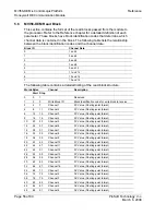
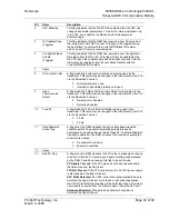
Words Bytes
Channel
Description
Start
Stop
46
92
95
Channel 7
SV Value (Floating-point format)
48
96
99
Channel 8
SV Value (Floating-point format)
50
100 103
Channel 9
SV Value (Floating-point format)
52
104 107
Channel 10
SV Value (Floating-point format)
54
108 111
Channel 11
SV Value (Floating-point format)
56
112 115
Channel 12
SV Value (Floating-point format)
58
116 119
Channel 13
SV Value (Floating-point format)
60
120 123
Channel 14
SV Value (Floating-point format)
62
124 127
Channel 15
SV Value (Floating-point format)
64
128 131
Channel 16
SV Value (Floating-point format)
66 132
133 All
Channels
PV Update Flag (1 bit for each channel with
1=updated)
67 134
135 All
Channels
PV Timeout Flag (1 bit for each channel with
1=timeout, 0=normal)
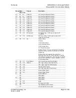
68 136
137 N/A
Module
Status
0: All OK
1: DE CPU Init Error
2: DE CPU Reset Error
3: DE Timeout Error
5: FTA Not Connected
If Status Codes 1 to 3 are received, the module has
detected a failure condition in at least one of the DE
processors.
If Status Code 5 is received, the module has
determined that the FTA is not connected. Verify the
connection and plug back in. The module will clear the
error condition itself and continue operation once the
FTA is reconnected.
69
138 141
First Channel
LRV: lower range value (Float format)
71
142 145
in Block
URV: upper range value (Float format)
73
146 149
URL: upper range limit (Float format)
75
150 153
Damping (Float format)
77
154 157
LRL: lower range limit (Float format)
79
158 159
Device Status Flags 1
80
160 161
Device Status Flags 2
81
162
Special DB Byte
163
Status Bits 1
82
164
Status Bits 2
165
Status Bits 3
83 166
167
Spare
84
168 169
PV Value 0 to 16383
85
170
Cfg Database update counter
171
Communication error counter


