Reference MVI56-DEM
♦
ControlLogix Platform
Honeywell DE Communication Module
ProSoft Technology, Inc.
Page 43 of 80
March 6, 2008
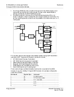
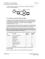
The following illustration shows the data transfer method used to move data
between the ControlLogix processor, the MVI56-DEM module, and the DE
instruments.
As shown in the previous diagram, all data transferred between the module and
the processor over the backplane is through the input and output images. Ladder
logic must be written in the ControlLogix processor to interface the input and
output image data defined in the controller tags. The user is responsible for
handling and interpreting all data received on the application ports and
transferred to the input image.
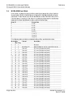
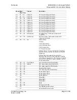
As blocks are transferred between the module and the processor, each block
contains a block identification code that defines the content or function of the
block of data transferred. The block identification codes used by the module are
displayed in the following table:
Block ID
Type
Description
0 to 1
Write Block
Data transferred from the processor to the module containing
configuration data to pass to the instruments. Each block contains
data for 8 channels. Block 0 contains the data for channels 1 to 8.
Block 1 contains the data for channels 9 to 16.
0 to 7
Read Block
Data transferred from the module to the processor. Each block
contains status data, real-time data and data for 2 channels. Block 0
contains the data for channels 1 and 2. Block 1 contains the data for
channels 3 and 4. Block 7 contains the data for channels 15 and 16.
9999
Write Block
Forces the module to perform a cold-boot operation.
Block identification codes 0 to 1 for write and 0 to 7 for read move the channel
data between the module and the processor. Block identification code 9999 is
used as a special control block to control the module. Each of these blocks are
discussed in the following topics:


