


Installing and Configuring the Module
MVI56-DEM
♦
ControlLogix Platform
Honeywell DE Communication Module
ProSoft Technology, Inc.
Page 21 of 80
March 6, 2008
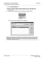
The last step in the module setup is to add the ladder logic. If the example ladder
logic is used, adjust the ladder to fit the application. When the ladder example is
not used, copy the ladder logic shown in the Controller Organization window to
the application.
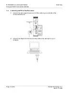
The module is now set up and ready to be used with your application. Insert the
module in the rack and attach the serial communication cable to the
debug/configuration port and connect the cable from the module to the FTA and
24 VDC power supply.
Download the new application to the controller and place the processor in run
mode. If the module is attached to the FTA, and DE instruments are present, the
module's Application LED (APP LED) should blink or remain on and the
backplane activity LED (BP ACT) should blink rapidly. Refer to the
Troubleshooting
section if you encounter errors. Attach a computer or terminal
to the debug port on the module and look at the status of the module using the
Configuration/Debug Menu in the module.


