MVI56-DEM
♦
ControlLogix Platform
Reference
Honeywell DE Communication Module
Page 40 of 80
ProSoft Technology, Inc.
March 6, 2008
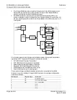
The Shared RAM provides a mailbox through which the MVI processor and
the two DE processors can communicate. Access to this Shared RAM is
strictly controlled by the MVI56-DEM processor
The DEM module is connected to a Field Terminal Assembly (FTA), not
shown in diagram, which includes 250 ohm range resistors to convert the 4 to
20 ma current signals from the Smart Transmitters in the DE mode into 1 to 5
Volt signals
DE CPU
#1
68HC11
Receiver 1
Receiver 8
Write to DE
Instrument
Circuitry
Shared Ram
for data
exchange
Primary
DEM
controller
Allen
-Bradley
Backplane
Transfer
circuitry
Read
C
ommand
Write
Command
DE CPU
#2
68HC11
Receiver 9
Receiver 16
Write to DE
Instrument
Circuitry
To FTA
then to
instruments
Isolation
Barrier
The module supports both Single and/or Multi-variable Honeywell Transmitters
operating in DE. Supported Honeywell instruments include:
ST 3000 Smart Pressure Transmitter
STT 3000 Smart Temperature Transmitter
SMV 3000 Smart Multivariable Transmitter
MagneW 300 Smart Magnetic Flow meter
SCM 3000 Smart Coriolis Mass Flow meter
SGC 3000 Smart Gas Chromatograph
There can be Single and Multi-Variable instruments connected to the DEM
module, in any mix, totaling 16 logical DE Channels. An example configuration
could be as follows:
DE Channel
Physical Type
Instrument
1
SV
ST 3000 Pressure
2
SV
STT 3000 Temperature
3
MV
PV 1 - SMV 3000
4
PV
2
5
PV
3
6
PV
4


