8
3.4 OPERATION OF THE PNC-01 DIGITAL CONTROL
PANEL
3.4.1 Operation of the Model PNC-01 Digital Control Panel
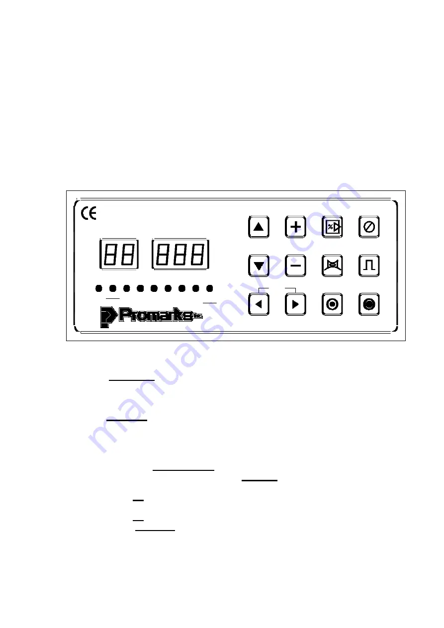
When following the instructions for programming your machine please refer
to Fig.5 below.
Figure 5
PRO G RA M
PROGRAM
TIME / %
SK IP
CY CLE
STO P
CY CLE
STB
W O RK
V A C
G A S
SEA L1 SEA L2 CO O L SO FT G A S
SH IFT
G A S
O N /O FF
PU LSE
O N /O FF
O IL CH G
A IR O N /O FF
PU LSE
PU RG E
PO W ER O N
PO W ER O FF
Standard Machine – Basic Instructions
A
. Press the
Main Power
switch located to the right of the control panel.
1. The Main Power switch will
NOT
light up.
2. The standby,
STB, LED
on the control panel will light up.
B
. Press the
Power ON
touch pad on the control panel.
1. The
Program
display and the
Time/%
display will light up.
2. The
Program
display will indicate what program the machine is running.
3. The
Time/%
display will indicate the vacuum setting for that program.
C. Changing to a different program
1. Press either the
Up or the Down
arrow key on the control panel.
2. You will see the number displayed in the
Program
display change.
3. Select the program number before the one you want to move to
4. Press the
Up
arrow key and hold it down for approximately 5 seconds.
5. You will see the number in the
Program Display
begin to blink.
6. Press the
Up
arrow key once and it will stop blinking.
7. Using the
Up / Down
arrows go back to the program number you chose.
8.
Important:
Cycle the machine 1 time to save program change.
Summary of Contents for DC-800
Page 19: ...16 ...
Page 23: ...20 5 3 PNEUMATIC DIAGRAM ...
Page 24: ...21 5 4 ELECTRICAL DIAGRAM FB ...
Page 25: ...22 5 4 ELECTRICAL DIAGRAM TB ...
Page 27: ...6 1 BODY 24 DC80100000 Body Diagram ...
Page 29: ...6 2 WORKING BED BOTTOM 26 C C Working bed Bottom Diagram DC80200000 ...
Page 32: ...6 3 1 CUSHION BAR FB 29 Cushion Bar Diagram D80K2FB000 ...
Page 34: ...6 3 2 CUSHION BAR FBG 31 D80K2FBG00 Cushion Bar Diagram ...
Page 36: ...6 3 3 CUSHION BAR FBPK 33 D80K2PK000 Cushion Bar Diagram ...
Page 38: ...6 3 4 CUSHION BAR FBPKG 35 D80K2PKG00 Cushion Bar Diagram ...
Page 40: ...6 3 5 SEALING BAR BOTTOM FBTB 37 DC802TB000 Sealing Bar Bottom Diagram ...
Page 42: ...6 3 6 SEALING BAR BOTTOM FBTBG 39 DC802TBG000 Sealing Bar Bottom Diagram ...
Page 44: ...6 3 7 SEALING BAR BOTTOM FBTBPK 41 D80K2TK000 Sealing Bar Bottom Diagram ...
Page 46: ...6 3 8 SEALING BAR BOTTOM FBTBPKG 43 D80K2TKG00 Sealing Bar Bottom Diagram ...
Page 48: ...6 4 CHAMBER LID DIAGRAM 45 Chamber Lid Top Diagram DC80300000 ...
Page 50: ...6 5 1 SEALING BAR TOP FB 47 D80K312A00 Sealing Bar Top Diagram ...
Page 53: ...6 5 2 SEALING BAR TOP PK 50 DC80350A00 Sealing Bar Top Diagram ...
Page 56: ...53 6 6 ELECTRICAL BOX FB 6 6 ELECTRICAL BOX TB ...


