Promac 348C Instruction Manual Download Page 20

Settings


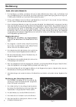
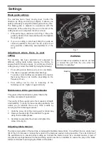
Blade guide settings


The  machine  has  a  freely  moving  lever  to  alter  the 
direction  by  lifting  and  turning  it  slightly.  It  allows  you 
quickly and easily to adjust the blade guide at any time. 
The  blade  guide  is  adjusted  in  accordance  with  the 
dimensions of the  parts. Only the one on the left of the 
cutting head can be adjusted; the other is fixed.


1.  If the part is large, undo lever (A) of Fig. 7. Move the 

guide by about 2.5 cm towards the part, then tighten 
the lever again.


2.  If  you  are  cutting  a  small  part  bring  the  guide  as 

close  as  possible  to  the  part.  The  two  types  of  cut 
will  guarantee  satisfactory  accomplishment  of  the 
work.


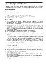
Adjustment  where  there  is  poor 
cutting


The  machine  has  been  adjusted  and  subjected  to 
different  cutting  tests  before  leaving  the  factory  to 
ensure that it functions properly. If you discover that it is 
cutting poorly, correct the defect by doing the following:


1.  Poor cutting due to blade wear: put in a new blade.


2.  The saw is equipped with fixed ball bearings.


To ensure correct cutting, we recommend to replace 
them  every  three  or  six  months,  depending  on  the 
frequency of use.


3.  Poor  cutting  can  be  due  to  loosening  of  the 

fastening nut (A). Tighten it again correctly.


Fig. 7


WARNING


Do  not  make  any  adjustment  and  do  not load 
or  unload  the  part  from  the  vice  when  the 
machine is operating!


Bearing


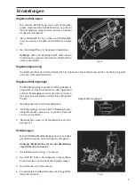
Maintenance of the gear transmission


The gears of the transmission system fitted to the 
machine are made of special steel.


The quality of these gears gives them superior strength 
and durability. To keep the saw  operating optimally,  we 
advise  you  to  lubricate  them  every  three  months  by 
carrying out the following procedure:


1.  Undo the screw (A) of Fig. 8 using an 8 mm Allen key.


2.  Remove the wheel (B), then lubricate the gears 

using thermostable grease.


3.  Carefully re-assemble the wheel, and tighten the 


screw correctly (A).


Fig. 8


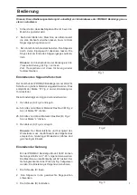
Adjusting blade tension 


The tensioning system of the machine is designed to facilitate interventions. It is sufficient to turn control lever 
(B) of Fig. 6 to increase or reduce the tension of the blade as needed, during operation. The main function of 
this  adjustment  is  to  ensure  perfect  cutting  as  it  allows  the  blade  to  work  at  a  constant  tension.  A  pair  of 
compression springs fastened to the tensioning system are there in addition to reduce the play of the blade. 
All this contributes to prolonging the lifetime of the latter.


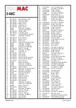
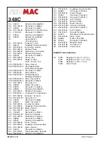
Summary of Contents for 348C

Page 1: ...C declaration of conformity 11 12 SafetyInformation 13 14 Special safety rules for the saw 15 Power supply 16 Specifications description of the machine 17 Quick Vice unpacking 18 19 Use 20 Settings 21...

Page 2: ...2 EC Maschinenrichtlnie Machines Directives 2014 30 EU elektromagnetische Vertr glichkeit electromagnetic compatibility 2014 35 EU Niedervolt Direktiven Low Voltage Directives und entspechend folgende...

Page 3: ...on der Maschine entfernen Ein Verhalten entwickeln dass immer vor dem Einschalten der Maschine gepr ft wird ob alle losen Bedienelemente entfernt wurden 5 Arbeitsbereich hindernisfrei halten Verstellt...

Page 4: ...Medikamenten oder Drogen bedienen 23 Sicher stellen dass die Maschine von der Netzversorgung getrennt ist bevor Arbeiten an den elektrischen Anlage am Antriebsmotor etc erfolgen Hinweise zur Arbeitssi...

Page 5: ...le Lage ausgef hrt werden Die Einstellungen dazu sind einfach vorzunehmen EMPFEHLUNG DER MASCHINE 1 Die Maschine dient zum Schneiden von metallischen Bauteilen von unterschiedlichem Pro l und Form die...

Page 6: ...er Probleme mit dem Motor haben wenden Sie sich an Ihre PROMAC Servicestelle zur berpr fung der Maschine 6 Verl ngerungskabel m ssen der nebenstehenden Tabelle entsprechen Ist der Querschnitt des Kabe...

Page 7: ...on grobem Material eingestellt worden Dies entspricht der Marke H Fig 2 an der Einstellung der Torsionsfeder Diese Einstellung kann folgend ver ndert werden 1 Den Bolzen A Fig 2 entriegeln 2a Schnitte...

Page 8: ...abdek kung ist die Maschine von Stromnetz zu tren nen 1 Den S gearm in die 90 stellen danach den Griff A Fig 4 ziehen und den S gearm in die vertikale Position f hren Den Griff A einrasten lassen 2 Di...

Page 9: ...er wurden im Werk genaustens eingestellt Ist das Spiel zwischen dem S geband und den F hrungslagern mehr als 0 2mm m ssen die Lager erneuert werden Achten Sie auf folgende Punkte 1 Das S geband darf n...

Page 10: ...nen und das Zahnrad mit einem z h ssigem hochwertigem Fett BLASO LUBE 304 oder hnliches schmieren 5 Bandrad wieder montieren und die Radschraube A festziehen 6 Alle Abdeckungen und Schutzvorrichtungen...

Page 11: ...attached parts in the vicinity of moving components 5 Clear sufficient workspace around the machine Cluttering of work benches or manoeuvring zones inevitably causes accidents 6 Do not use the machine...

Page 12: ...n to transport the machine Work station 1 There should be sufficient lighting and ventilation for the work area 2 The lighting should be at a level of 300 LUX to guarantee proper work Noise level In c...

Page 13: ...ds 1 It is imperative to choose a blade suited to the material and type of cut planned The saw is equipped with a bimetallic blade which can be used for cutting stainless steel steel iron brass alumin...

Page 14: ...a time If your saw makes unusual noises or vibrates excessively stop it immediately Turn the saw off Unplug it Do not restart it until the problem has been located and been remedied 2 Never hold on t...

Page 15: ...ry to start the motor again If the motor still does not start refer to the Motor Troubleshooting table 3 If the motor suddenly locks when cutting wood release the trigger unplug the tool and remove th...

Page 16: ...sure greatly extends the life of the blade 5 The drive is effected via a gear transmission which ensures more regular more powerful and smoother cutting which is better than those of all the pulley dr...

Page 17: ...on the wheel at the end of the base 3 Place the part on the saw bench If it is long support the end of it Unpacking and checking the contents The metal hacksaw comes complete in a box Remove all pack...

Page 18: ...ion The feed rate is adjusted for cutting thinner metal tubing Oblique cut The machine uses a pivoting mitre block for oblique cuts from 0 to 45 degrees The pivot arm has an an index A in Fig 4 The ma...

Page 19: ...it to the right Run the blade through by pulling it downwards with one hand It will align itself properly on the wheels 7 Replace the blade guards and cover G Start the machine to check if the blade...

Page 20: ...n the frequency of use 3 Poor cutting can be due to loosening of the fastening nut A Tighten it again correctly Fig 7 WARNING Do not make any adjustment and do not load or unload the part from the vic...

Page 21: ...s connection needs to be changed this must be done by an electrician Elektrische Teile Electrical components Zeichen Designation Beschreibung Description and function Typ Type Tech Daten Spec Normen S...

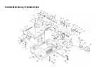
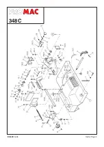
Page 22: ...Ersatzteilzeichnung Exploded view...

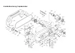
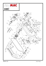
Page 23: ...Ersatzteilzeichnung Exploded view...

Page 24: ...348048C Mutter Nut 48A PM 348048D Hebel Lever 49 PM 348049 Keil Cotter 50 PM 348050 Welle Shaft 24 51 PM 348051 Keil Cotter 4x4x12 52 949254 Schraube Screw M6x16 53 PM 348053 Platte Plate 54 PM 348054...

Page 25: ...6 2 Feder Spring M6 126 3 PM 348126 3 Schraube ScrewM6x8 127 PM 348127 Schraube Screw 128 949560 Mutter Nut M10 129 949334 Schraube Screw M5x16 130 942864 Federring Washer M5 131 PM 348131 Schalter Tr...

Page 26: ...cument we undertake to repair the article mentioned below under guarantee for a period of 24 months from the date This guarantee will not be honoured if this duly completed certificate is not returned...

Page 27: ...l article d sir H ndlernachweis Renseignements sur les revendeurs Schweiz Suisse TOOL AG 8117 F llanden Tel 044 806 59 59 Fax 044 806 59 69 e mail tool tool ag ch www promac fr Frankreich France TOOL...

Page 28: ...doivent tre effectu s par un technicien 348C Zeichen Beschreibung Modell Tech Daten Normen Divers Symbol Fonction Mod le Donn s techn Normes divers XP Netzstecker LT 322 250VAC IEC 309 1 SEV Fiche 5 1...

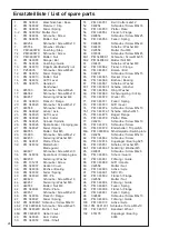
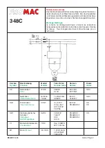
Page 29: ...Seite Page 3 EX 609 06 05 348C...

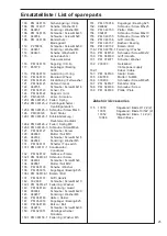
Page 30: ...Seite Page 4 EX 609 06 05 348C...

Page 31: ...Clavette 4x4x12 52 949254 Schraube Vis M6x16 53 PM 348053 Platte Plaque 54 PM 348054 Flansch Flasque 55 949656 Schraube Vis M8x25 56 PM 348056 Feder Ressort 57 949630 Schraube Vis M8x40 58 949433 Sche...

Page 32: ...casse 132 1 PM 348132 1 Schraube Vis 133 949334 Schraube Vis M5x6 134 949561 Mutter Ecrou M12 135 PM 348135 Scheibe Rondelle 136 PM 353016 Kugellager Roulement 625 136 1 PM 348136 1 Bolzen Boulon 137...

Reviews: