


5
SMARTBATIP
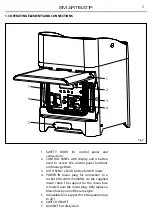
1.3 OPERATING ELEMENTS AND CONNECTIONS
1. SAFETY DOOR for control panel and
connections
2. CONTROL PANEL with display and 4 button
used to access the control panel functions
and manage them.
3. AUTO SYNC/ CLEAR button for WiFi mode
4. POWER IN mains plug for connection to a
socket (100-240V~/50/60Hz) via the supplied
mains cable. The support for the mains fuse
is located near the mains plug. Only replace a
blown fuse by one of the same type.
5. Adjustable foot support for tilt regulation (up
to 20°).
6. SWITCH ON/OFF
7. MAGNET for safety door
Fig.2
2
1
7
6
3
4
5
Summary of Contents for SMARTBATIP
Page 1: ...MANUALE UTENTE USER MANUAL SMARTBATIP IT EN PORTABLE BATTERY POWERED UPLIGHTER...
Page 38: ......
Page 39: ......