


4
normally be because of the oil pressure gauge, given
that if it fails to receive a signal from this gauge, the
unit will understand that the engine is already working.
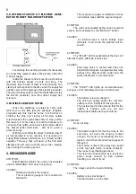
3.4. ACTIVATION BY EXTERNAL ORDER
When the Diesel-Control is delivered without
clock, and thus, is destined for activation by other
units, it will dispose of an input (terminals 1 and 2) for
these.
In this case it will be necessary to leave the
outlet to be used by these external units free of
tension.
The Diesel-Control, on receiving a signal will
initiate the start and when the signal ceases it will
activate the stop. Because of this, it will keep the
engine activated while there is a contact on inputs 1
and 2.
Even when the unit includes a clock, it can carry
out starts and stops obeying level sensors, or similar,
by way of inputs 2, 3 and 4. (External signals always
free of tension). In these inputs the cables can be of 1
or 1.5 mm2 cross-section.
These inputs, differently from number 1 and 2
before, are independent for starts and stops and,
furthermore, only function with the initial impulse of a
signal or contact.
There use will be useful when the start has to be
by clock and the stop by level indicator (inputs 2 and
4); or when the activation is by sensor (inputs 2 and 3)
and the stop by clock; or when their is external
activation and deactivation by way of differentiated
impulses for start and stop.
In input 6 (breakdown) any kind of sensor with a
normally open contact, free of tension can be
connected. The cross-section of the cable can also be
either 1 or 1.5 mm2.
3.5. OUTLETS
Terminal no. 1 (common outlet) must be
connected directly to the positive battery terminal. The
cross-section of this cable can be 2.5 mm2.
The outlet for activating the starter motor
(terminal 2) has a relay with a maximum intensity of
10ª (as have the remaining outlets).
However, it is necessary to install a
supplementary relay between this outlet and the
starter motor. Follow the instructions which appear
later.
This terminal has to be connected to one pole
of the supplementary starter relay winding. The other
pole has to be connected directly to the negative.
These cables can be of 1.5 mm2 cross-section.
The starter relay common outlet must be
connected directly to the positive with a direct 6 or 8
mm2 wire. The other contact must be connected to
the distributor with a similar wire.
There are engines which need to work with
double injection by way of a small electro-magnet
which will be connected in parallel with the starter.
The stop outlet (terminal 3) can act directly
without a relay in between, through an electro-valve
(which will temporarily cut the fuel supply) with a
1.5mm2 cable.
The stop electro-valve will be installed between
the filter and as close as possible to the injector input
and will normally be open and at 12v DC.
The engine can also be stopped by way of an
electro-magnet (which chokes the engine).
If the electro-magnet system is chosen, a
supplementary relay must be installed. The
connecting up of the Diesel-control and the relay and
that of this to the electro-magnet will be carried out in
the same way as in the case of the start. It being
possible to bridge the negatives of the relay windings
and the positives of the common outlets of the
contacts, with the same sections as specified above.
The contact outlet (terminal no. 4 will remain
activated from the moment of starting until the stop.
The contact outlet gives positive whenever the
unit is working (“WORKING” LED illuminated). This
outlet will only be used in case we need to activate a
general aperture electro-valve, or when the engine
needs the contact signal to charge the battery.
In this case it can be connected directly to the
contact position of the starter key.
At the contact outlet, an electro-valve for
irrigation can be connected if necessary.
Use 35 mm2 cross-section cable as normally
used in the motor industry from the battery negative to
the engine chassis. This section should be increased if
the distance between the battery and the engine is
greater than 3 metres.
The connection to the engine or the support
must be good. An adequate place could be where the
rectifier negative connects to the earth 9.
The cable from the positive to the starter motor
terminal should have a cross-section of 20 mm2, for a
distance not greater than 4 metres, so that the tension
drop on starting the engine is minimum; this way the
battery charge will also be used to its maximum by the
alternator.
For the connection of Diesel-control, it would be
convenient if all the cables had terminals, by which a
greater degree of security and a better appearance
would be achieved in the connections, thus also
avoiding poor connections which occasionally causes
false contacts.
Avoid producing short-circuits in the cables
given that the unit does not contain fuses (to avoid
tension drops in the same).


