


3
PROGRAMATION
Adapt the gantries of programming moving
them out (for the time that you want the engine to be
active) or pressing to put them in.
SETTING IN TIME
Use the command “F” of working of spheres
and pointers, avoiding moving them directly. For the
setting in time, consider the index of operations “G” as
much as the pointers; thus, if we want to select 15
hours, the index of operations “G” should have to
indicate 15,00 and the pointers should be at the
position that the figure indicates.
In the double sphere clocks, have to be
programmed the internal and the external sphere.
WARRANTY
The unit is warranted against manufacturing
defects for two years.
Breakdowns caused by accidents, mis-
connection and unauthorised use are excluded from
this warranty.
2. TECHNICAL CHARACTERISTICS
PROTECTION
Protection against polarity changes in the feed
input.
Protection against power surges.
Protection against the chance activation of the
starter when the engine is working.
UNIT CONSUMPTION
Stopped 0.0025 A (0,03 W).
Working 0,0600 A (0,70 W).
PERMITTED WORKING TEMPERATURES
From -5 º C to +45 º C.
COMPONENTS
C-MOS integrated circuits. 10 A relay outlet.
MOUNTING BOX
Metal with lock, 25x25x8.
3. INSTALLATION
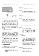
3.1. WALL MOUNTING
4 pieces for wall mounting are supplied with the
unit, which are mounted, from the outside and without
need to open the unit, in the holes on the back of this.
Site the engine, battery and DIESEL-CONTROL
as close as possible to each other, bearing in mind
possible problems which might arise such as, for
example, a water leak from the pump wetting the unit,
engine vibrations, etc...
3.2. CONNECTIONS
To connect the unit, remove the “connection
housing” cover.
3.3. INPUTS
Feed the unit 12v DC (INPUT terminals 7 and 8)
respecting the polarity.
The connection should be made with 2.5 mm2
cross-section cables, with direct feed from the battery
terminals, without any other connection between these
two points.
On connecting the unit to the battery, wait about
3 minutes before beginning any working operation. If
any warning light stays lit, press the MANUAL STOP
button and the unit will be prepared to initiate the
starter sequence.
Input no. 5 (STARTER DETECTOR) must be
connected directly to the oil pressure gauge,
prescinding any other connection (for example, the oil
warning light). To make the connection, first
disconnect the pressure gauge and do not reconnect
it as, if not, the unit could be damaged. The cable
cross-section should be 1.5 mm2.
When the unit does not obey start orders, it will


