


2
activated from when the first attempt at starting is
made until the stop.
An electrovalve for irrigation can also be
connected to the contact outlet.
Optionally, the unit can be supplied with a
warm-up function. In this case, it will have a button for
programming the warm-up timing on the front, which
will function before the activation of the starter motor.
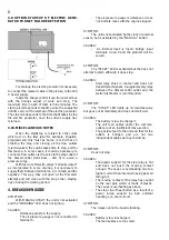
FUNCTION DIAGRAM
STOP
The stop can be caused:
a)
By the end of the timing programmed on
the clock.
b)
By obeying external elements such as,
for example, level sensors, irrigation
programmers, etc.
c)
Manually (“MANUAL STOP” button).
d)
By the detection of a breakdown by a
sensor connected to the corresponding
input (motor overheating, oil pressure,
lack of water, etc.), this being recorded
by the illuminated indicators (“SENSOR
BREAKDOWN”).
STOP FUNCTION THEORY
The stop is carried out by the activation of an
outlet, for a short period of time, which can be
connected to an electro-valve (cut in the fuel supply)
or an electro-magnet (choking the engine).
It is advisable to mount the electro-valve, for the
stop, on the engine, between the filter and the injector.
Stop time is adjustable from 6 to 90 seconds
(“STOP” button).
The setting for the stop timing should be left at
least 30 % longer than the time the engine actually
takes to stop.
BREAKDOWN DETECTION
Breakdowns will only be detected from one and
a half minutes after the engine has actually started.
On detecting a breakdown through the sensors
or in the oil pressure, the unit will automatically
activate the stop relay, also keeping the “SENSOR
BREAKDOWN” indicator lit although the breakdown
disappears. This will only go out on restarting. engine
again. However, if the breakdown continues, the unit
stop the
OPTIONS
WITHOUT CLOCK. In this option, the unit
incorporates a start/stop input for possible connection
to programmers or other external elements.
WITH ONE DAY CLOCK, which repeats the
programmes every day. In this option, 15 minute
intervals between orders are possible.
WITH WEEKLY CLOCK, which repeats the
programmes daily or weekly.
In this model, the intervals between orders are two-
hourly.
WITH DOUBLE SPHERE CLOCK, which repeats
the programmes daily or weekly, as in the “WEEKLY”
version, but with 30 minute intervals between orders.
WITH DOUBLE OUTLET DIGITAL CLOCK,
which allows orders by minutes and with daily or
weekly frequency. It has 2 outlets for, per example,
working with two different irrigation sectors, or with
only one but with independent fertilizer application.
WITH PRE-HEATING. With this option, the unit
preheats the engine before each attempt at starting.
CLOCK
The Diesel Control can incorporate different
kinds of clocks. If they are digital, moreover of this
manual, there is one about the clock. If they are
analogical (of gantries) you can follow these
instructions:
ACTIVATION STOP
RELAY.
DEACTIVATION OF
WORKING INDICATOR
STOP
WORKING
STARTER TIMING
ACTIVATION
CONTACT AND
WORKING
INDICATOR: 1
ST
START ATTEMPT
1 ½ MINUTE WAIT
MOTOR HAS
STARTED
1 ½ MINUTE WAIT
IS IT THE
4
TH
ATTEMP
T
ACTIVATION OF
STARTER BREAKDOWN
INDICATOR
BREAKDOWN
ACTIVATION OUTLET
ACTIVATION SENSOR
BREAKDOWN INDICATOR
SI
YES
NO
NO
NO
YES


