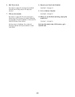
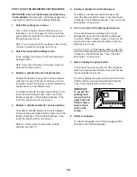
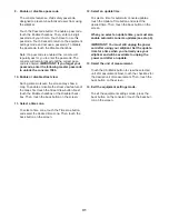
background image

16

THE CHEST HEART RATE MONITOR

HOW TO PUT ON THE HEART RATE MONITOR

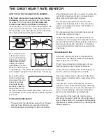
If the heart rate monitor looks like the one shown 

in drawing 1, press the transmitter (A) onto the snap 

fasteners on the chest strap (B). If the heart rate 

monitor looks like the one shown in drawing 2, 

insert the tab (C) on one end of the chest strap (D) into 

one end of the transmitter (E). Then, press the end of 

the transmitter under the buckle (F) on the chest strap; 

the tab should be flush with the transmitter.

Next, wrap the heart 

rate monitor around 

your chest in the loca-

tion shown; the heart 

rate monitor must be 

under your clothes, 

tight against your skin. 

Make sure that the logo 

is right-side-up. Then, attach the other end of the chest 

strap. Adjust the length of the chest strap, if necessary.

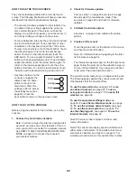
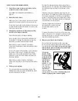
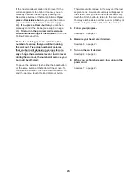
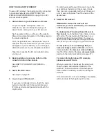
Next, pull the trans-

mitter and the chest 

strap away from your 

body a few inches 

and locate the two 

electrode areas (G). 

Using saliva or con-

tact lens solution, wet the electrode areas. Then, return 

the transmitter and the chest strap to a position against 

your chest. 

CARE AND MAINTENANCE

•  Thoroughly dry the electrode areas with a soft towel 

after each use. Moisture may keep the heart rate 

monitor activated, shortening the life of the battery.

•  Store the heart rate monitor in a warm, dry place. Do 

not store the heart rate monitor in a plastic bag or 

other container that may trap moisture.

•  Do not expose the heart rate monitor to direct 

sunlight for extended periods of time, and do not 

expose it to temperatures above 122°F (50°C) or 

below 14°F (-10°C). 

•  Do not excessively bend or stretch the heart rate 

monitor when using or storing it.

•  To clean the transmitter, use a damp cloth and a 

small amount of mild soap. Then, wipe the transmit-

ter with a damp cloth and thoroughly dry it with a soft 

towel. Never use alcohol, abrasives, or chemicals 

to clean the transmitter. Hand wash and air dry the 

chest strap.

TROUBLESHOOTING

•  If the heart rate monitor does not function when 

positioned as described at the left, move it slightly 

lower or higher on your chest.

•  If heart rate readings are not displayed until you 

begin perspiring, re-wet the electrode areas.

•  For the console to display heart rate readings, you 

must be within arm’s length of the console.

•  If there is a battery cover on the back of the trans-

mitter, replace the battery with a new battery of the 

same type.

•  The heart rate monitor is designed to work with 

people who have normal heart rhythms. Heart rate 

reading problems may be caused by medical condi-

tions such as premature ventricular contractions 

(pvcs), tachycardia bursts, and arrhythmia.

•  The operation of the heart rate monitor can be 

affected by magnetic interference from high power 

lines or other sources. If you suspect that magnetic 

interference is causing a problem, try relocating the 

fitness equipment.

1

2

A

B

E

F

C

D

G

Summary of Contents for PFEVEL12716.0

Page 1: ...r reference Serial Number Decal www iconeurope com CUSTOMER SERVICE UNITED KINGDOM Call 0330 123 1045 From Ireland 053 92 36102 Website www iconsupport eu E mail csuk iconeurope com Write ICON Health...

Page 2: ...EMBLY 7 THE CHEST HEART RATE MONITOR 16 HOW TO USE THE ELLIPTICAL 17 MAINTENANCE AND TROUBLESHOOTING 35 EXERCISE GUIDELINES 37 PART LIST 39 EXPLODED DRAWING 41 ORDERING REPLACEMENT PARTS Back Cover RE...

Page 3: ...n each side To protect the floor or carpet from dam age place a mat under the elliptical 8 Inspect and properly tighten all parts each time the elliptical is used Replace any worn parts immediately 9...

Page 4: ...wheel stops Reduce your pedaling speed in a controlled way 19 Keep your back straight while using the ellip tical do not arch your back 20 Over exercising may result in serious injury or death If you...

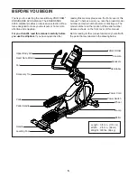
Page 5: ...f this manual To help us assist you note the product model number and serial number before contacting us The model number and the location of the serial number decal are shown on the front cover of th...

Page 6: ...er following the key number is the quantity needed for assembly Note If a part is not in the hardware kit check to see if it has been preassembled Extra parts may be included M10 x 122mm Screw 104 4 M...

Page 7: ...With the help of a second person place some of the packing materials not shown under the rear of the Frame 1 Have the second person hold the Frame to prevent it from tipping while you complete this st...

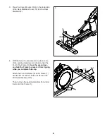
Page 8: ...ce some of the packing materials not shown under the front of the Frame 1 Have the second per son hold the Frame to prevent it from tipping while you complete this step Attach the Front Stabilizer 6 t...

Page 9: ...Upright Tip To prevent the Main Wire 110 from fall ing into the Upright 4 secure the Main Wire with the wire tie A 1 4 110 A A 110 5 6 6 Tip Avoid pinching the Main Wire 110 Avoid damaging the indica...

Page 10: ...0 onto the right side of the Pivot Axle 35 Repeat these actions for the Left Upper Body Leg 46 Then tighten an M8 x 13mm Screw 82 and an M8 Washer 97 into each end of the Pivot Axle 35 at the same tim...

Page 11: ...right 4 connect the wires on the Console to the Main Wire 110 and to the Sensor Wires 63 Insert the excess wire into the Upright 4 110 10 10 Tip Avoid pinching the wires Attach the Console 7 to the Up...

Page 12: ...edal Arm Axles 64 Next slide an M8 Washer 97 and an Axle Spacer 77 onto an M8 x 13mm Screw 82 and tighten the Screw a few turns into the Pedal Arm Axle 64 While a second person holds the front end of...

Page 13: ...by pressing it onto the Rear Upright Cover 81 101 81 117 4 14 14 Identify the Right Arm Front Cover 65 and ori ent it as shown Attach the Right Arm Front Cover 65 to the Right Upper Body Leg 60 with...

Page 14: ...wn Attach the Right Leg Outer Cover 69 around the Right Upper Body Leg 60 by pressing it onto the Right Leg Inner Cover 83 Repeat this step on the other side of the elliptical 60 94 101 69 15 83 75 11...

Page 15: ...over 79 around the Upright 4 by pressing it onto the Rear Console Cover 80 79 4 80 101 17 18 19 Make sure that all parts are properly tightened before you use the elliptical Extra parts may be include...

Page 16: ...plastic bag or other container that may trap moisture Do not expose the heart rate monitor to direct sunlight for extended periods of time and do not expose it to temperatures above 122 F 50 C or belo...

Page 17: ...lug the indicated end of the power cord into the socket on the frame 2 Plug the power cord into an appropriate outlet that is properly installed and earthed in accordance with all local codes and ordi...

Page 18: ...he elliptical rocks slightly on your floor during use turn one or both of the leveling feet beneath the rear of the frame until the rocking motion is eliminated HOW TO USE THE TABLET HOLDER IMPORTANT...

Page 19: ...that is in the lower position Then step onto the other pedal Push the pedals until they begin to move with a continuous motion Note The pedals can turn in either direc tion It is recommended that you...

Page 20: ...omizable Google Maps Download training workouts designed to help you reach your personal goals Measure your progress by competing against other users in the iFit community Upload your workout results...

Page 21: ...dio books with the console sound system while you exercise In addition you can use the charging port on the con sole to charge your USB compatible device while you exercise To turn on the power see th...

Page 22: ...d use some other features of the con sole you must be connected to a wireless network See HOW TO USE THE WIRELESS NETWORK MODE on page 33 to connect the console to your wireless network 2 Check for fi...

Page 23: ...y mode that you select will determine which workout information is shown To select the desired display mode simply flick or slide the screen You can also view additional work out information by touchi...

Page 24: ...esired The fan has several speed settings including an auto mode While the auto mode is selected the speed of the fan will automatically increase or decrease as your pedaling speed increases or decrea...

Page 25: ...and incline settings of the workout 4 Start the workout Touch the Start Workout button to start the workout Each workout is divided into segments One resistance level one incline level and one tar ge...

Page 26: ...our weight In addition if you manu ally change the resistance level or incline level during the workout the number of calories you burn will be affected To pause the workout touch either the back butt...

Page 27: ...e level and or incline level for the current segment is too high or too low you can manually override the setting by pressing the Resistance buttons or the Ramp buttons If you press a Resistance butto...

Page 28: ...assword and touch the Login button To switch users within your iFit account touch the user button at the bottom of the screen If more than one user is associated with your iFit account a list of users...

Page 29: ...ur progress Touch the buttons on the screen to select the desired map options During a race or challenge the screen will show your position in the race relative to other competitors 8 Measure your hea...

Page 30: ...pdates first touch the Auto Update button Next touch the Enable checkbox or the Disable checkbox Then touch the back button on the screen Note To select a time for automatic console updates see step 1...

Page 31: ...ext touch the Enable checkbox or the Disable check box Then touch the back button on the screen 11 Select a time zone To select a time zone touch the Timezone button and select the desired time zone T...

Page 32: ...s designed to improve your exer cise experience 4 Calibrate the incline system Touch the Calibrate Incline button Then touch the Begin button to calibrate the incline system The ramp will automaticall...

Page 33: ...etworks appears touch the desired network Note You will need to know your network name SSID If your network has a password you will also need to know the password An information box will ask if you wa...

Page 34: ...d in Note The charging port cannot be used to view or transfer data or to play music through the console sound system HOW TO USE THE INTERNET BROWSER Note To use the internet browser you must have acc...

Page 35: ...4 on page 32 and calibrate the incline system HOW TO ADJUST THE REED SWITCH If the console does not display correct feedback the reed switch should be adjusted To adjust the reed switch first press th...

Page 36: ...dy Leg 60 Next remove the M8 x 16mm Screw 95 the Large Axle Cover 53 and the M8 Washer not shown from the right Crank Arm 20 Then carefully remove the Right Pedal Arm 58 and the Right Roller Arm 59 fr...

Page 37: ...c Exercise If your goal is to strengthen your cardiovascular system you must perform aerobic exercise which is activity that requires large amounts of oxygen for prolonged periods of time For aerobic...

Page 38: ...lles Stretch With one leg in front of the other reach forward and place your hands against a wall Keep your back leg straight and your back foot flat on the floor Bend your front leg lean forward and...

Page 39: ...Pedal 53 4 Large Axle Cover 54 2 16mm Wave Washer 55 2 Small Axle Cover 56 4 Roller Arm Bushing 57 8 Arm Bearing 58 1 Right Pedal Arm 59 1 Right Roller Arm 60 1 Right Upper Body Leg 61 1 Right Upper B...

Page 40: ...123 1 Plastic Spacer 124 2 M4 x 19mm Self tapping Screw 125 2 Bumper 126 2 M8 x 14mm Shoulder Screw 127 1 Tablet Holder 128 1 Left Pedal Plate 129 1 Left Pedal Handle 130 2 Pedal Pin 131 2 Pedal Sprin...

Page 41: ...101 101 50 43 43 48 23 84 50 31 27 82 101 78 78 86 86 88 90 85 85 89 90 50 90 91 102 108 108 113 120 121 121 121 121 121 122 102 115 32 114 101 17 123 112 2 28 30 30 33 33 105 104 101 101 6 34 34 124...

Page 42: ...68 101 62 64 64 65 67 70 72 69 83 87 76 77 77 77 101 101 77 95 95 95 95 82 82 126 82 82 82 82 96 94 94 97 97 97 97 97 97 97 97 100 100 100 100 101 103 102 101 133 135 136 136 135 135 103 128 56 56 59...

Page 43: ...ODED DRAWING C 36 36 99 99 35 37 81 54 54 63 71 74 79 73 75 80 105 105 139 101 101 5 140 5 107 101 139 101 5 5 5 5 140 101 110 119 118 116 116 117 4 101 101 101 7 111 127 71 137 Model No PFEVEL12716 0...

Page 44: ...ACEMENT PARTS Part No 380139 R0516A Printed in China 2016 ICON Health Fitness Inc This electronic product must not be disposed of in municipal waste To preserve the environment this product must be re...

Reviews: