background image

MULTIMETRE MEDIUM 


EN - 2 

PIN-116  

2

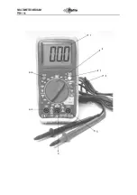
. Insert the banana plug of the black testing wire in 

the negative 

(3)

COM connection and the banana 

plug of the red testing wire in the po 

(5) 

connection (

).  

3

. Touch the circuit or wire you want to check with 

the test probe tips. 

4

. If the resistance is lower than approx. 100 


 an 

acoustic signal is sounded. The display will also 
show the actual resistance. 
 

Diode test 
 
Warning! 

To avoid electric shocks do not test live 

diodes. 
 
1.Insert the banana plug of the black measuring 
cable in the negative (3) (COM) input, and the 
banana plug of the red measuring cable in the 
positive diode input (5). 

2

. Set the switch to  

3

. Place the measuring heads on the diode to be 

tested. The conductor voltage is 400 to 700mV. The 
reverse voltage is shown by “1”. Short-circuit 
appliances give a result close to 0 mV. An open 
appliance is shown by “1” for both poles. 
 

Measurements of AC/DC current intensity 
 
Warning! 

To prevent electric shocks you may not 

measure AC current intensities in circuits with a 
voltage of over 250V AC. 
 

Caution! 

Do not conduct current measurements in 

the 10A range that last longer than 30 seconds. If 
they last longer than 30 seconds this can cause 
damage to the metre and/or testing wires. 
 

1

. Insert the banana plug of the black testing wire in 

the negative

(1)

COM connection. 

2. 

For power measurements up to 200 mA DC, set 

the function switch to the highest DC mA position, 
and insert the banana plug of the red measuring 
cable in the (mA) input. 

3. 

For power strengths of 10 A DC, set the function 

switch to 10A, and insert the banana plug of the red 
measuring cable in the 10A input. 

4

. Switch the voltage of the circuit to be tested off 

and open the circuit at the point where you want to 
measure the current intensity. 

5

. Touch the negative side of the circuit with the 

black test probe. Touch the positive side of the 
circuit with the red test probe.  

6

. Put power on the circuit. 

7

. Read off the current intensity on the display. The 

display will show the correct decimals, value and 
symbol. 

 
Temperature measurements 
 
Warning! 

To prevent electric shocks you must 

disconnect both test probes from any power sources 
before you measure the temperature. 
 

1

. If you want to measure the temperature in 

(

F

)arenheit, switch the function switch to the °F 

position. If you want to measure the temperature in 

(

C

)elcius, switch the function switch to the °C 

position.  

2

. Insert the banana plug of the thermocouple probe 

in the negative 

(3) COM 

connection and the plug of 

the red wire in the positive 

(5) 

Temp diode 

connection. 

3

. Touch the part you want to measure the 

temperature of with the end of the temperature 
probe. Hold the probe against the part to be tested 
until the measured value stabilises (approx. 30 
seconds). 

4

. Read off the temperature on the display. The 

digital measured value will show the correct 
decimals and value. 

 
Warning! 

To prevent electric shocks check that the 

thermocouple has been removed before you 
proceed with another measuring operation. 
 

Replacing the battery 
 
Warning!

 To prevent electric shocks you must 

disconnect the testing wires from any power sources 
before you open the cover of the battery 
compartment.  
 

1

. When the batteries are nearly empty the 

message "BAT" appears on the right of the display. 
The battery must then be replaced. 

2

. Follow the instructions for replacing batteries. 

See the paragraph on changing the battery in this 
manual. 

3

. Dispose of old batteries at a collection point. 


Warning! 

To prevent electric shocks you may not 

use the metre until the cover of the battery 
compartment has been replaced and fastened. 
 

Placing batteries 
1.

 Disconnect the metre's testing wires. 

2

. Remove the rubber housing 

3.

 Open the battery cover by removing the screw 

with a screwdriver. 

4.

 Place the battery in the compartment. Ensure the 

correct polarity. 

5.

 Replace the battery cover. Fasten using the two 

screws. 

Note.

: If your metre is not functioning properly you 

must check the fusing and the battery to make sure 
they are still in working order and correctly fitted. 
 

Summary of Contents for 730660341

Page 1: ...DIGITALE MULTIMETER MEDIUM MULTIMETRE DIGITAL MEDIUM PIN 116...

Page 2: ......

Page 3: ...aansluiting en de stekker van de rode draad in de positieve 5 aansluiting voor metingen hoger dan 10A of in de positieve 10A aansluiting 4 voor metingen lager of gelijk aan 10A 2 Raak met de testsond...

Page 4: ...nnen voordat u de temperatuur meet 1 Wanneer u de temperatuur wilt meten in F arenheit zet u de functieschakelaar in de F stand Wanneer u de temperatuur wilt meten in C elcius zet u de functieschakela...

Page 5: ...nts LCD display Polariteit Automatisch indicatie negatieve polariteit Diverse Grafieken DC spanning VDC Bereik Resolutie Nauwkeurigheid 200mV 0 1mV 2000mV 1mV 0 5 van rdg 2 cijferig 20V 0 01mV 200V 0...

Page 6: ...e Attention Ne mesurez jamais des tensions DC au moment o un moteur est allum ou teint sur le circuit Ceci peut en effet provoquer des pics de tension importants susceptibles d endommager le multim tr...

Page 7: ...circuit sous tension 6 Lisez l intensit l cran L cran affiche la valeur avec une pr cision d une d cimale et le signe correct Mesures de temp rature Attention Afin d viter les chocs lectriques il con...

Page 8: ...m tre avant d avoir referm et verrouill le couvercle du compartiment fusibles Sp cifications Cat gorie de surtension CATII Affichage Affichage LCD 2000 comptes Polarit Automatique indication de polari...

Page 9: ...switched ON or OFF This can cause large voltage peaks that could damage the metre 1 Switch the function switch to the V DC position Insert the banana plug of the black testing wire in the negative 3...

Page 10: ...circuit 7 Read off the current intensity on the display The display will show the correct decimals value and symbol Temperature measurements Warning To prevent electric shocks you must disconnect bot...

Page 11: ...hocks you may not use the metre until the cover of the fuse compartment has been replaced and fastened Specifications Overvoltage category CATII Display 2 000 counts Polarity Automatic indication nega...

Page 12: ...ste um die Funktion zu beenden Gleichspannungsmessungen DC Achtung Messen Sie keine Gleichspannungen wenn ein Motor im Stromkreis EIN oder AUSgeschaltet wird Dadurch k nnen gro e Spannungsspitzen ents...

Page 13: ...Funktionsschalter auf 10 A und stecken den Bananenstecker des roten Messkabels in den 10 A Eingang 4 Schalten Sie die Spannung des zu testenden Stromkreises aus und ffnen Sie anschlie end den Stromkre...

Page 14: ...neue Sicherung in den Halter ein 6 Verwenden Sie immer eine Sicherung in der entsprechenden Gr e und mit den richtigen Spezifikationen 10A 250V schnell reagierend f r den 10A Bereich 7 Setzen Sie die...

Page 15: ...tensi n continua Atenci n No mida ninguna tensi n DC cuando conecte AAN o desconecte UIT un motor en el circuito Esto podr a provocar fuerte picos de tensi n que podr an da ar el medidor 1 Ponga el in...

Page 16: ...eba roja toque el lado positivo del circuito 6 Abra la tensi n del circuito 7 Lea el amperaje en la pantalla La pantalla mostrar el punto decimal correcto el valor y el s mbolo correspondiente Medicio...

Page 17: ...es El instrumento cumple la norma EN61010 1 Aislamiento clase 2 doble aislamiento Categor a de sobretensi n CATIII 600V CATII 1000V Pantalla pantalla LCD de 6000 cuentas con indicador de funci n Polar...

Page 18: ...al pode causar grandes picos de tens o que podem danificar o medidor 1 Coloque o interruptor de fun o na posi o V CC Introduza a ficha do fio de teste preto na 3 liga o COM negativa e a ficha do fio v...

Page 19: ...enta o antes de medir a temperatura 1 Se pretender medir a temperatura em F arenheit coloque o interruptor de fun o na posi o F Se pretender medir a temperatura em C elcius coloque o interruptor de fu...

Page 20: ...o 600 0mV 0 1mV 0 5 de rdg 2 d gitos 6 000V 1mV 60 00V 10mV 600 0V 100mV 1 2 de rdg 2 d gitos 1000V 1V 1 5 de rdg 2 d gitos Tens o CA Gama Resolu o Precis o 6 000V 1mV 1 5 de rdg 10 d gitos 60 00V 10m...

Page 21: ...4 F 1400 F 1 F 3 de rdg 5 C 9 F Sensor Par termoel ctrico de Tipo K Protec o de sobrecarga 600V CC ou CA rms Teste de d odo Corrente de teste Resolu o Precis o 0 3mA t pica 1mV 10 de rdg 5 d gitos Te...

Page 22: ...un motore Possono derivarne elevati picchi di tensione che potrebbero danneggiare l apparecchio 1 Posizionare il selettore di funzione su V DC Inserire la spina a banana del cavo di test nero nell ing...

Page 23: ...isurazioni di temperatura Avvertenza Per prevenire il rischio di elettroshock prima di misurare la temperatura scollegare entrambe le sonde di test da eventuali sorgenti di tensione 1 Se si desidera m...

Page 24: ...tegoria di sovratensione CATIII 600V CATII 1000V Display LCD 6000 counts con indicazione di funzione Polarit automatica indicazione polarit negativa Fuori range indicazione OL Risposta AC vero RMS 50...

Reviews: