


502 069 02
44/79
Power Monitor, PD 3260
Manual
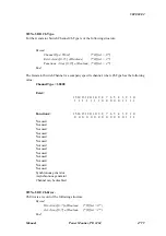
Enablebit:
7 6 5 4 3 2 1 0
Not used
Not used
Not used
Not used
Not used
Not used
Switch Error
Input Simulation
During an attempt to connect a generator to a power line, it may be that the module fails to switch,
because zero phase shift between line and generator does not occur within the phase speed
difference range, as defined in the StartSpeed variable. A Switch Error indicates that switching
has failed, and the generator frequency has accelerated beyond the line frequency by the frequency
difference specified in StartSpeed. Detection of Switch Error is enabled by setting
ChConfig.EnableBit[1] to true.
In input simulation mode, no variables in the channel are automatically calculated and no variable
values will be overwritten by the module. This makes it possible to simulate any value in a
variable for test purposes. Input simulation is enabled by setting ChConfig.EnableBit[0] to true.
Functions:
The functions field is used in a hexadecimal format, where the most significant digit is used to
specify the channel functions.
Functions = $00 => Channel disabled.
Functions = $10 => Asynchronous generator switch.
Functions = $20 => Synchronous generator switch.
If the channel is not used, the channel should be disabled by writing "00" in ChConfig.Functions.
Otherwise errors may occur.
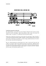
Asynchronous generator switch (Functions = $10)
The generator speed and acceleration is measured with a tachometer connected to the DI 8
terminal. Digital I/O 8 must be configured as an input: Functions = $00. The moment when the
generator will achieve the configured StartSpeed is calculated and compensated by the configured
DelayComp.
The switch function is enabled by setting FlagReg.SwitchEnable = True. The output selected in
Ref_A is switched on at the calculated instant, and is switched off by setting
FlagReg.SwitchEnable= False.