background image


Page 26 


5.3.2 Main menu 

The main menu is located on the left side of the main screen. It contains seven 
different buttons: 


Measure:


Measuring mode 

Project:


Create and open projects and measuring files 

Calibrate:


Calibration of measuring head, speed calibration 

Camera:


Camera settings 

Settings:


System configuration, filter settings, marking presettings 

Info:


Errors and warnings, system information 

Close:


Close program 


Please refer to the following chapters for a detailed explanation. 
 

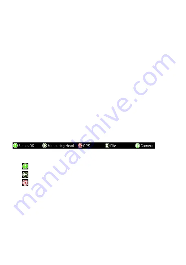
5.3.3 Status bar 

The status bar is located at the bottom of the main window. It contains five icons 
which indicate the current state of the corresponding system component (from left 
to right): 


1.  Errors and warnings 
2.  Measuring head 
3.  GPS 
4.  Measuring file 
5.  Camera 


The different colours have the following meaning: 
 

  Light green:  Component active or connected 

  Dark green:  Component inactive or neutral 

  Red: 

Error, warning or component not connected 


Summary of Contents for ZDR 6020

Page 1: ...ZDR 6020 Dynamic Retroreflectometer RL for the following versions 6020 EU 1m and 6020 OV 1m Instruction Manual...

Page 2: ......

Page 3: ...mponents 15 4 1 General overview 15 4 2 Measuring head 16 4 3 External connectors 17 4 4 Carrier pipe 18 4 5 Tablet docking station and tablet mount 18 4 6 Camera 20 4 7 Panel switches 21 4 8 Storage...

Page 4: ...ngs 38 5 8 3 Event button configuration 39 5 8 4 Camera settings 39 5 8 5 Bar Graph settings 41 5 8 6 System configuration 41 5 8 7 Admin 45 5 9 Info 45 5 9 1 Messages 45 5 9 2 System info 46 6 Measur...

Page 5: ...Page 5 10 3 Replacing the lamp 60 10 4 Replacing the protective glass 65 10 5 Replacing the fuse 65 11 Error messages 66 12 Technical specification 67 Glossary 69...

Page 6: ...q SA to update Some of the images shown in this instruction manual may be of a pre production model and or are computer generated therefore the design features of the delivered product may differ in v...

Page 7: ...type of spreadsheet software can be used for further analysis of the measurements The included mapping and data analysis software MappingTools is used for graphical visualization and one click generat...

Page 8: ...e ZDR 6020 Dynamic Retro reflectometer RL measures the Retroreflection of road markings true to scale RL is the coefficient of retroreflected luminance night visibility of road markings The observatio...

Page 9: ...the ZDR 6020 must read and understand the manual completely In particular the safety precautions and warnings The ZDR 6020 is exclusively intended for the determination of night visibility RL for all...

Page 10: ...d annunciates Furthermore authorizations and or escort vehicles may be needed to measure Do not get distracted by the operation of the device Always concentrate on the traffic situation Lack of attent...

Page 11: ...c This superficial checking of the goods has to be done within a time limit set by the carrier which is normally 7 days However this period may vary depending on the courier Hence it is recommended to...

Page 12: ...pters left right for measuring head mounting 1 Ruggedized touchscreen tablet with installed ZDR 6020 RetroGrabber software and microphone 1 Tablet docking station 1 Tablet mount 1 Calibration unit wit...

Page 13: ...Set of tools 6 Allen keys 1 5 mm 2 mm 2 5 mm 3 mm 4 mm 5 mm 1 Allen screw M4 2 Spanner wrenches 10 mm 19 mm 1 each 1 Screwdriver type Allen key 5 mm 2 Set of spare parts 1 Halogen lamp 1 Set of fuses...

Page 14: ...flectometer RL Qd ZRM 6006 Retro reflectometer RL Qd All spare parts can be purchased from Proceq or an authorized agent Proceq SA refuses all warranty and liability claims for damages caused by usage...

Page 15: ...ablet docking station and tablet mount Camera Panel switches Power supply unit car box Storage box Calibration unit Wiring The ZDR 6020 Dynamic Retro reflectometer RL may be operated by one or by two...

Page 16: ...ta acquisition process Furthermore it streams the measured values to the RetroGrabber software on the tablet White front light 3 Status LEDs Auxiliary laser factory use only Observation optics Mountin...

Page 17: ...is connected to the system by a heavy duty industrial plug connector They are located next to the rear wheel on either side of the measuring vehicle see picture below The connector pins are protected...

Page 18: ...espectively External connector Carrier pipe Fasteners Protective cap for console Angle adjustment screw Mounting adapter Fasteners Quick release 4 5 Tablet docking station and tablet mount A ruggedize...

Page 19: ...gged into the docking station Ethernet connector Power docking station When driving with the tablet mount in place the passenger side airbag should be deactivated It is forbidden to operate the vehicl...

Page 20: ...e button Camera in the RetroGrabber software To get good quality pictures adjust the focus and zoom angle by turning the corresponding ring on the lens The camera has a built in auto iris thus it adju...

Page 21: ...g head The boot up procedure may take as long as 20 seconds It is ready to operate when the yellow status LED on the measuring head is blinking The measuring head is only powered when the main switch...

Page 22: ...contains the measuring head the mounting adapters all tools and spare parts Storage box Black aluminium frame Calibration unit Power supply unit car box Auxiliary height indicators Sunshade Allen keys...

Page 23: ...ng different components of the system Most fuses are located in the power supply unit car box The system runs on 12 VDC It is connected to the car battery and protected by a 40 A fuse which is usually...

Page 24: ...wiring between the different system components is installed once and is invisible to the user Most cables go to the power supply unit car box and don t need to be manipulated for normal measuring oper...

Page 25: ...val Storing the measured value together with additional information in the measuring file 5 1 Installation For the current version the software needs to be installed and configured at our premises 5 2...

Page 26: ...and warnings system information Close Close program Please refer to the following chapters for a detailed explanation 5 3 3 Status bar The status bar is located at the bottom of the main window It co...

Page 27: ...t established a connection to the RetroGrabber software icon in the status bar is dark green a black window is displayed As soon as the measuring head has established a connection to the RetroGrabber...

Page 28: ...ontrol measurements or comparisons with a handheld device The full range of features is displayed in the measuring window only when a project and a measuring file have been opened or created please re...

Page 29: ...bar means good signal quality Note Despite this bar showing bad quality for short periods the measuring result still may be fine Only if the bar is empty all the time this indicates a bad signal caus...

Page 30: ...folder and choosing the file with zdp file extension On the tablet a project is a folder containing subfolders and different files Commonly they are stored in Libraries Documents RetroGrabber A projec...

Page 31: ...ompulsory Region Measuring area optional Street Street name optional Lane Lane name optional Start Position Start position km of measurement default 0 Side Lane position optional Driver Name Name of t...

Page 32: ...the measuring file in Microsoft Excel This is because the file is not a native Excel file but a tab separated text file see above Click Yes to open the file The header section contains the measuring...

Page 33: ...n km h Reference Not used GPS Long Start GPS longitude at interval start format 0 000000 GPS Lat Start GPS latitude at interval start format 0 000000 GPS Long GPS longitude at interval end format 0 00...

Page 34: ...alibration Stationary calibration mode default mode Dynamic Calibration Calibration with moving vehicle Setup button Calibration settings and speed calibration Calibrate button Calibrate measuring hea...

Page 35: ...Setup Speed Calibration in the main menu to open the speed calibration window The button is disabled if the measuring head is not connected to the system New Calib New speed calibration Recalibrate R...

Page 36: ...he road markings The system is configured to take a picture every 10 meters Click on Camera in the main menu to open the camera window to see a live picture 5 7 1 Camera properties The camera properti...

Page 37: ...presettings are used to store measurement parameters for a marking The marking presettings can be prepared in the office before measuring and then be applied on site When a marking presetting is appl...

Page 38: ...Markings less wide will not be measured default 80 Expected max width Maximum width of marking Wider markings will not be measured default 280 RL Pass Fail min value Minimum RL value of a marking low...

Page 39: ...rst three buttons have a punctual setup which means the event will only be written once into the measuring file when pressed The other seven buttons have a linear setup which means the event will be w...

Page 40: ...and adjust the mileage accordingly Take always Pictures Takes pictures every 10 m Apply Marking Presetting Takes a picture if the RL value is below or above the camera values in the marking presetting...

Page 41: ...t recognized as markings 5 8 6 System configuration There is no need to change the settings in this window for normal operation Only use this window if you are asked to do so by an administrator More...

Page 42: ...ection Calibration Monitor Calibration parameters internal use only GPS Monitor GPS temperature and humidity State Machine Internal use only Filter Settings Before an RL value is calculated and displa...

Page 43: ...discarded Marking width filter Enable disable filter Min width in bars Lower limit marking not valid if lower Max width in bars Upper limit marking not valid if higher MarkingGapsFilter Number of gap...

Page 44: ...thin an interval that must have passed all filters default 10 CutFromTopForMean Percentage of the highest measurements to be eliminated noise reduction default 2 TakeForMeanFromTop Percentage of measu...

Page 45: ...stration area for internal use only 5 9 Info Errors warnings and general system information Click on Info in the main menu to open the info window 5 9 1 Messages Errors and messages are displayed and...

Page 46: ...tion RetroGrabber Version RetroGrabber software version Serial Number Serial number of measuring head Target Address IP of measuring head Measuring head Version Measuring head hardware version Realtim...

Page 47: ...lves placing the tablet in the docking station starting the RetroGrabber software and attaching and levelling the measuring head Follow the guide below to set up the system Put the lever on the dockin...

Page 48: ...he carrier pipe Open the protective cap on the external connector by pushing back the safety clamp underneath Slide the mounting adapter with the nozzle on top into the carrier pipe The left mounting...

Page 49: ...k the quick release fastener Quick release fastener locked Start the RetroGrabber software then switch on Head on the panel and wait approx 20 seconds until the RetroGrabber has connected to the measu...

Page 50: ...r switch Laser radiation class 2 Avoid direct eye contact to beam Place the corresponding auxiliary height indicator next to the centre of the front and rear wheel so that the laser beams are visible...

Page 51: ...llen key to adjust the height of the measuring head The quick release fastener must be unlocked when moving the screw Angle adjustment screw on the mounting adapter Use the screwdriver type 5 Allen ke...

Page 52: ...ential to get good measuring results Use a flat and even spot for calibration Make sure you use the same marking presetting for calibration as for measuring see chapter 5 8 1 on page 37 Make sure the...

Page 53: ...seated The yellow mark must be in level with the calibration unit Adjust position and height of the calibration units front part so that the laser beam is passing the little hole in the white screen...

Page 54: ...lue in the Setup if necessary Press Calibrate The calibration process takes a couple of seconds Accept the calibration if the deviation does not exceed 5 Otherwise discard it Make sure the measuring h...

Page 55: ...6 2 on page 47 It is recommended to do a calibration each time the measuring head is mounted or at least once a day see chapter 6 3 on page 52 It is also recommended to prepare all projects and measur...

Page 56: ...suring Having reached the point where you want to start to measure press Capture and the software will then record the measurement information on the tablet At the end of the measuring area press Capt...

Page 57: ...aight as possible a motorway is best suited As all mileage and speed information is derived from that calibration the length of the reference distance must be as accurate as possible In the RetroGrabb...

Page 58: ...Used for internet connections while working in the office The measuring head will not connect when NetSetMan is set to Office Do not forget to switch to ZDR 6020 profile before setting up the system 8...

Page 59: ...manual for more information For RetroGrabber Versions 3 0 x and 3 1 x the following steps must be taken in order to import the measuring file into the MappingTools software Version 1 25 or older Go to...

Page 60: ...nts such as cleaning agents for glass benzene acetone Furthermore we recommend cleaning the instrument periodically using water and oil free compressed air max 1 5 to 2 bar Do not use strong acids or...

Page 61: ...spare lamps are aligned optically and then glued to the lamp holder part This alignment process may only be performed at Proceq SA Factory Open the measuring head housing 1 Loosen the three screws on...

Page 62: ...all other fingers The measuring head should now begin to slide out of the housing gradually Alternative solution If the head doesn t slide out easily try the following Screw the M4 screw from the sto...

Page 63: ...then push back the air outlet part by squeezing the flexible tube together When the flexible tube is squeezed the lamp with its holder is laid open Gently pull the lamp out of the fit it is sitting i...

Page 64: ...ng the lamp Afterwards place the air outlet part into its position Make sure this part sits in its fit correctly as well You may check whether the parts sit in their fit correctly by sliding over the...

Page 65: ...rey storage box The 40A main fuse is located near the car battery It protects the feed line from the car battery to the power supply unit car box Please refer to the wiring schematics in chapter 4 11...

Page 66: ...not connected Unable to connect to the measuring head Make sure the current NetSetMan profile is set to ZDR 6020 Restart the system Check the LEDs at the network plug of the docking station 7210 LAN...

Page 67: ...r error Unable to write parameters to specified measuring file Make sure the measuring file exists and you have write permission Make sure the measuring file is not open in another program like MS Exc...

Page 68: ...orage temperature 15 C 60 C 5 F 140 F Humidity non condensing Dimensions LxWxH measuring head 270 mm x 207 mm x 310 mm 10 63 x 8 15 x 12 2 power supply unit car box 360 mm x 150 mm x 450 mm 14 17 x 5...

Page 69: ...ages 66 Event button configuration 39 Exclusion of liability 6 Extent of delivery 12 External connectors 17 F Features 7 Filter settings 42 Fuse Replacing 65 G General overview 15 I Info 45 Instrument...

Page 70: ...tem 47 Settings 37 Shipment 11 Software 25 47 66 Installation 25 Main screen 25 Start up 25 Specifications 68 Speed Calibration 57 Standard delivery 12 Storage Temperature 68 Storage box 22 System com...

Page 71: ......

Page 72: ...Subject to change Copyright 2017 by Proceq SA Schwerzenbach All rights reserved www proceq com Version 2 6 dated 15 06 2017...

Reviews: