Hi-Fi
tuner
proSTL1EYE
Coupler
From
starBOX
Short flylead
(supplied)
LED
Page 5
Page 4
Single extension room (stand-alone application)
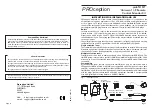
The installation wiring diagram for the basic single-extension system is shown in
Fig. 2
.
The wiring steps for this application are as follows:
1. Divert the aerial lead from the main TV to the IN connector of the base unit.
2. Connect the longer flylead supplied between the TV connector of the base unit and
the TV aerial socket.
3. Run a coaxial cable connection from the OUT connection of the base unit to IN
connector of the coupler in the extension room. The coaxial connectors supplied in
the kit will need to be fitted to the ends of the cable (see coaxial connectors on Page
5). Note that the female connector is used at the base unit end (master location) and
the male connector at the extension room end.
4. Connect the TV end of the coupler to the TV via the shorter flylead supplied.
5. Position the receiver eye on top of the TV, or in a suitable nearby location, facing
toward the seating or TV viewing area of the room.
Now connect the power unit and emitters (or blaster) to the base unit and you should
have a working system see the notes on tuning and testing below.
Multiple extension rooms (starBOX systems)
Typical master location wiring is shown in
Fig. 3
for Sky* or Sky+* systems and
Fig. 4
for
a Freeview
system. (These diagrams assume that the starBOX system has been installed
in accordance with the instructions supplied.) Note that a new flylead (not supplied) will
be required to connect between the base unit (OUT) and the RETURN input socket on the
master outlet plate.
In all cases the input to the base unit should come from the final item of source equipment
in the signal chain, and the return feed to the starBOX must be taken directly from the
OUT connector of the base unit.
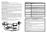
Extension room wiring is shown in
Fig. 5
. Take care to ensure that the coupler is connected
the right way round (the IN and TV connectors are clearly marked). Where a dual TV &
radio outlet plate is installed in the extension room, as shown in the figure, take care to
connect the coupler and TV to the TV side of the plate. If further set-top TV equipment,
such as a local VCR or Freeview
box, is to be used in an extension room it should be
connected between the coupler and the TV. The output channel from such equipment will
only be available in that extension room.
Fig. 5 Extension room wiring (showing optional VHF radio tuner).
Eye installation with an existing TV
Where an extension room already has a TV installed follow these steps to install the
starLINK eye:
1. Unplug the aerial lead from the TV and plug it into the female IN connector of the
coupler.
2. Plug the male TV connector of the coupler into the TVs aerial socket via the short
flylead provided.
3. Position the receiver eye on top of the TV, or in a suitable nearby location, facing
toward the seating or TV viewing area of the room.
4. Select a VCR or set-top box channel on the TV and check that remote control operation
of the relevant source equipment is working.
General installation notes
Base unit and power supply
The base unit should be fixed to a wall, skirting board or similar surface using the fixings
provided. Connect the output of the power supply to the base unit before connecting the
the power unit to the mains supply.
The power unit supplied is for use with a standard UK (BS 1363) mains socket-outlet only.
Before connecting this equipment to the mains supply, read the safety instructions on
page 7. Disconnect the power unit from the mains whenever the equipment is to remain
unused for long periods of time.
Emitters or blaster
One emitter device should be stuck to the front of each item of source equipment. The
exact positioning is not usually very critical, but it is recommended to experiment with the
position of each emitter (see the section below on testing) before sticking it in place. The
emitter housings are transparent to infra-red and do not interfere with normal local
operation of the equipment. The low-tack sticky pads supplied in the kit allow the emitters
to be removed easily when necessary.
The emitters plug into the jack connectors on the top of the base unit. Up to two emitter
pairs may be connected. If one of the emitters of a pair is unused it should be tucked
away behind the equipment. Do not cut an unused emitter off the wiring harness as this
will stop the other one working (they are wired in series).
Separate instructions are supplied with the blaster accessory.
TV
Coaxial connectors
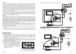
The connectors supplied may be used for the ends of the extension cable run in the
stand-alone (single extension room) application, or for making-up a flylead. The correct
method of fitting the connectors is illustrated in Fig. 6. For best results the use of a
double-screened (tape and braid) cable such as CT100-type or WF100 is recommended.
Fig. 6 Fitting the coaxial connectors
tighten terminal screw
for centre conductor
Braid wires folded back over cable
clamp (do not allow stray wires to
touch inner conductor) Remove cable
foil where necessary.
inner conductor
4 mm
10 mm


