Page 3
Page 6
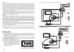
Fig. 3 Master location wiring for starBOX system with Sky+*
Fig. 4 Master location wiring for starBOX system
with a Freeview
receiver.
Tuning
In a new installation, extension room TVs will need tuning-in to the output channel(s)
from the source equipment at the master location (usually the main living room). To
tune-in these TVs leave a tape or disk playing on a VCR or DVD player, or select a known
channel on a digital receiver, then tune an unused channel setting on each of the remote
TVs into the video or digital programme. Repeat this procedure for each set-top item. For
instructions on how to tune a TV refer to its instruction manual or the manufacturers
help line or Web site. In starBOX systems similar tuning will be required for the CCTV
camera output, where installed.
If more than one item of set-top equipment is connected in the system you may experience
severe interference (patterning) when more than one output channel is present. In this
case the output channel number (modulator channel) for one or more items will need to
be changed, and the relevant TVs retuned.
Testing
Once installation is complete and TV pictures are available in all extension rooms, test
the system to ensure that remote control of each item of source equipment is working in
every extension room. For example, if you are watching a Freeview
or Sky* Digital channel
from a Freeview
or Sky* box in the living room it should be possible to control the
relevant box from any extension room equipped with a starLINK eye. The normal remote
handset for each item of equipment should be used (or alternatively a suitable universal
handset programmed for your equipment).
During testing you may need to experiment with the positioning of the eyes and/or emitters
to obtain reliable operation of the system. The LED indicators provided on the eye couplers
and base unit can help with testing:
n
The coupler LED should flash red whenever a remote control command is received by
the eye.
n
The base unit LED is a 2-colour device: green for power-on indication and red to
indicate when remote control commands are being received from an extension room.
Telephone line
Master outlet plate
ANT IN
Hi-Fi
tuner
Main TV
ANT IN
Freeview
RF OUT
MASTER OUT
LNB2 OUT
UHF RETURN
From starBOX
VCR
PSU
emitters
OUT
TV
Base unit
Long flylead
(supplied)
IN
ANT IN
RF OUT
Telephone line
Master outlet plate
ANT IN
Hi-Fi
tuner
Main TV
ANT IN
VCR
RF OUT-1
MASTER OUT
LNB2 OUT
UHF RETURN
From starBOX
Sky+
PSU
emitters
OUT
TV
Base unit
Long flylead
(supplied)
IN
ANT IN
RF OUT
LNB1
LNB2
Avoiding problems
Some dos and donts
n
Each eye should be positioned to face toward the viewing area of the room. Avoid
placing an eye where it could be exposed to full sunlight, or near other bright lights,
particularly compact fluorescent lamps. (These light sources could inhibit correct
operation of the infra-red receiver.)
n
Dont plug the coupler directly into the aerial socket of a TV, since its weight could
place excessive stress on the TVs connector and cause damage. Always use the short
flylead supplied for this purpose.
n
Dont cut off an unused emitter (see Page 5).
n
The signal connections to the extension rooms
must not include any isolated outlet plates.
These will not pass the power supply from
the base unit or starBOX to the eyes and will
need to be replaced to ensure correct
operation of the system.
Fig 7. Old isolated outlet plates are
not compatible with the starLINK system.


