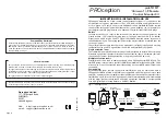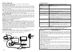
System components
This section gives a brief description of each part of the starLINK system.
Components supplied in this kit
Eye
located in the extension room, the infra-red receiver eye picks up remote control
commands and sends them back along the TV signal cable to the
base unit
. The eye
consists of two parts: the receiver eye itself and the
coupler
, which serves to connect the
eye into the signal cable.
Base unit
this is located near to the source equipment and serves three purposes.
Firstly it splits the signal to feed both the local (main) TV and the extension rooms, secondly
in a single-extension system it provides power to the remote eye and thirdly it interfaces
the commands from the extension rooms to the
emitters
or
blaster
.
Power supply unit (PSU)
a plug-in power unit (mains adapter) which provides DC
power for the base unit.
Emitters
the stick-on emitters, supplied in pairs, are small devices which attach to the
front of the source equipment you wish to control from the extension rooms. They plug
into the base unit and re-emit the infra-red commands relayed from the extension room(s).
Two emitter pairs can be connected to one base unit.
Sundries
fixings, coaxial plugs and flyleads.
Other accessories available
Additional eyes
in systems using the
PRO
ception starBOX RF hub, up to five or ten
extension rooms (depending on the starBOX model fitted) can be equipped with remote
control eyes. Additional eye kits are available separately (product code proSTL1EYE).
I-R blaster
the blaster accessory (product code proSTL1BLAST) is an alternative to the
stick-on emitters, useful where more than two items of source equipment need to be
controlled, or where the emitters are considered inconvenient. The blaster operates by
emitting higher-level infra-red radiation in a similar fashion to a remote control handset
and can be placed in the general vicinity of the source equipment.
Installation wiring
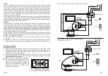
Typical installation wiring diagrams are shown in
Figs. 2 to 5
. These should be used as a
general guide to principles since the particular equipment installed will vary.
Fig. 2 Stand-alone application with a single extension room.
Page 7
Page 2
t
s
il
k
c
e
h
C
s
t
n
e
m
m
o
C
t
h
g
i
r
e
h
t
g
n
i
s
u
u
o
y
e
r
A
e
h
t
r
o
f
t
e
s
d
n
a
h
e
t
o
m
e
r
o
t
g
n
i
y
r
t
e
r
a
u
o
y
t
n
e
m
p
i
u
q
e
?
l
o
r
t
n
o
c
!t
s
ri
f
s
g
n
i
h
t
s
u
o
i
v
b
o
k
c
e
h
C
g
n
i
v
il
(
n
o
it
a
c
o
l
r
e
t
s
a
m
e
h
t
s
I
?
K
O
n
o
it
a
ll
a
t
s
n
i
)
m
o
o
r
y
lt
c
e
r
r
o
c
e
r
a
)
r
e
t
s
a
l
b
r
o
(
s
r
e
tt
i
m
e
d
n
a
ti
n
u
e
s
a
b
e
h
t
t
a
h
t
k
c
e
h
C
ll
i
w
e
r
e
h
s
m
e
l
b
o
r
P
.
s
m
a
r
g
a
i
d
g
n
ir
i
w
e
e
s
d
e
t
c
e
n
n
o
c
d
n
a
d
e
ll
a
t
s
n
i
.
s
m
o
o
r
n
o
i
s
n
e
t
x
e
L
L
A
n
i
n
o
it
a
r
e
p
o
t
c
e
ff
a
d
e
t
c
e
n
n
o
c
r
e
l
p
u
o
c
h
c
a
e
s
I
?
d
n
u
o
r
y
a
w
t
h
g
ir
e
h
t
t
u
b
,
K
O
e
b
ll
i
w
s
e
r
u
t
c
i
p
V
T
s
d
r
a
w
k
c
a
b
d
e
t
c
e
n
n
o
c
s
i
r
e
l
p
u
o
c
a
fI
.
k
r
o
w
t
o
n
ll
i
w
l
o
r
t
n
o
c
e
t
o
m
e
r
r
o
t
a
c
i
d
n
i
D
E
L
d
e
r
e
h
t
s
e
o
D
a
n
e
h
w
h
s
a
lf
r
e
l
p
u
o
c
e
h
t
n
o
?
d
e
s
s
e
r
p
s
i
n
o
tt
u
b
t
e
s
d
n
a
h
e
s
a
b
e
h
t
m
o
r
f
r
e
w
o
p
f
o
k
c
a
l
a
s
i
m
e
l
b
o
r
p
n
o
m
m
o
c
t
s
o
m
e
h
t
,t
o
n
fI
h
c
u
s
,
m
e
l
b
o
r
p
n
o
it
c
e
n
n
o
c
a
o
t
e
u
d
y
ll
a
u
s
u
s
i
s
i
h
T
.
X
O
B
r
a
t
s
r
o
ti
n
u
n
a
f
o
e
c
n
e
s
e
r
p
e
h
t
r
o
d
a
e
l
y
lf
d
e
g
a
m
a
d
,
g
u
l
p
x
a
o
c
d
e
tt
if
y
l
d
a
b
a
s
a
.
y
ll
u
f
e
r
a
c
s
n
o
it
c
e
n
n
o
c
ll
a
k
c
e
h
C
.)
e
v
o
b
a
t
x
e
t
e
e
s
(
e
t
a
l
p
t
e
lt
u
o
d
e
t
a
l
o
s
i
r
e
l
p
u
o
c
e
h
t
o
t
n
o
it
c
e
n
n
o
c
N
I
e
h
t
n
o
C
D
V
9
-
8
e
b
d
l
u
o
h
s
e
r
e
h
T
(
).
y
r
a
s
s
e
c
e
n
fi
r
e
t
e
m
it
l
u
m
a
h
ti
w
k
c
e
h
c
y
a
w
a
d
e
n
o
it
i
s
o
p
e
y
e
e
h
t
s
I
?
s
e
c
r
u
o
s
t
h
g
il
t
h
g
ir
b
m
o
r
f
V
T
e
h
t
r
o
(
s
p
m
a
l
t
n
e
c
s
e
r
o
u
lf
m
o
r
f
t
h
g
il
t
h
g
ir
b
r
o
t
h
g
il
n
u
s
t
c
e
ri
D
s
i
h
T
.
n
o
it
a
r
e
p
o
ti
b
i
h
n
i
n
a
c
e
y
e
r
e
v
i
e
c
e
r
e
h
t
n
o
g
n
il
l
a
f
)f
l
e
s
ti
n
e
e
r
c
s
-
e
r
y
b
t
n
e
m
ir
e
p
x
E
.
g
n
i
h
s
a
lf
r
o
t
a
c
i
d
n
i
D
E
L
s
r
e
l
p
u
o
c
e
h
t
p
o
t
s
o
s
l
a
ll
i
w
.)
s
p
m
a
l
r
o
(
e
y
e
e
h
t
g
n
i
n
o
it
i
s
o
p
h
s
a
lf
D
E
L
ti
n
u
e
s
a
b
e
h
t
s
e
o
D
n
o
i
s
n
e
t
x
e
n
a
n
e
h
w
d
e
r
?
d
e
t
a
r
e
p
o
s
i
t
e
s
d
n
a
h
m
o
o
r
e
h
t
d
n
a
)
T
U
O
(
ti
n
u
e
s
a
b
e
h
t
n
e
e
w
t
e
b
n
o
it
c
e
n
n
o
c
e
h
t
k
c
e
h
c
,t
o
n
fI
m
e
t
s
y
s
e
n
o
l
a
-
d
n
a
t
s
a
n
I
.
y
ti
u
n
it
n
o
c
C
D
r
o
f
)
N
R
U
T
E
R
F
H
U
(
X
O
B
r
a
t
s
.r
e
l
p
u
o
c
e
h
t
d
n
a
ti
n
u
e
s
a
b
e
h
t
n
e
e
w
t
e
b
y
ti
u
n
it
n
o
c
k
c
e
h
c
d
n
a
n
o
it
c
e
n
n
o
c
r
e
t
s
a
l
b
r
o
r
e
tt
i
m
e
e
h
t
k
c
e
h
c
,
h
s
a
lf
s
e
o
d
D
E
L
s
i
h
t
fI
.
g
n
i
n
o
it
i
s
o
p
ANT IN
PSU
ANT IN
RF OUT
emitters
OUT
TV
IN
Base unit
Main TV
UHF
aerial
proSTL1EYE (starLINK)
Coupler
Long flylead
(supplied)
RF OUT
VCR
Freeview
Coax plug (m)
Coax plug (f)
Short flylead
(supplied)
Troubleshooting hints
The following list may help if you are experiencing remote control problems.
OVERHEATING
The recommended ventilation clearances and other precautions given in the relevant section
of this instruction leaflet should be observed to prevent overheating. No unit should be fixed
where it is likely to become smothered by soft furnishing fabrics such as curtains, or by thermal
insulation material in a roof space or building void. Mains powered equipment should not be
left resting on a carpet.
WATER AND FIRE RISKS
Components of this kit are not waterproof. They are intended for indoor use only and must not
be placed where they could be exposed to dripping or splashing water. Objects containing
liquids should not be placed on or near the components.
To prevent risk of fire, no object with a naked flame should be placed on or near any of the
components or the associated wiring.
MAINS POWER SUPPLY UNITS
The power unit supplied as part of this kit is suitable only for use with 13 A sockets to BS 1363.
Consult a qualified electrician if the socket outlets in the location where the appliance is to be
installed are of a different type.
FIXED WIRING
Any fixed wiring installed to supply power to this system should comply with BS 7671 (IEE
wiring regulations, 16th Edition) and, where relevant, Part P of the building regulations. The
power unit is of Class 2 construction and does not require a protective earth connection. This
does not obviate the need to provide a circuit protective (earth) conductor in the supply wiring,
as required by BS 7671.
* Sky and Sky+ are registered trade marks of British Sky Broadcasting Group PLC.
Freeview is a registered trade mark of the British Broadcasting Corporation.
Safety Instructions


