background image

23

Î

Configuration


„

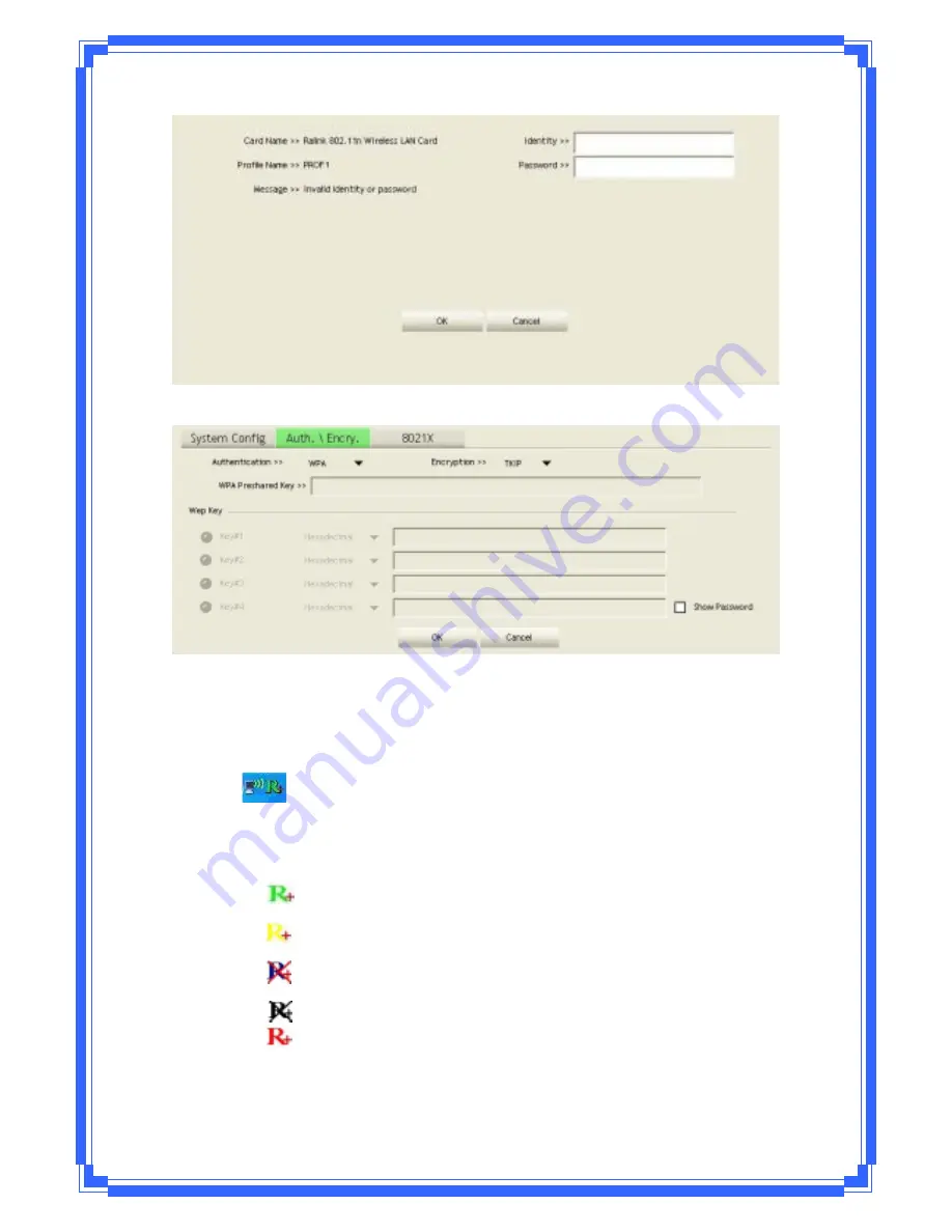
At

the

mean

time

of

starting

RaUI,

there

is

also

a

small

Ralink

icon

appears

within

windows

taskbar

as

below.

You

may

double

click

it

to

bring

up

the

main

menu

if

you

selected

to

close

RaUI

menu

earlier.

You

may

also

use

mouse;s

right

button

to

close

RaUI

utility.

ÎÎ

Ralink

icon

in

system

tray.

„

Besides,

the

small

icon

will

change

color

to

reflect

current

wireless

network

connection

status.

The

status

indicates

as

follow:

Î

 ͲͲ

indicate

Connected

and

Signal

Strength

is

Good.

Î

 ͲͲ

indicate

Connected

and

Signal

Strength

is

Normal

Î

 ͲͲ

indicate

Wireless

NIC

is

not

connected

yet

Î

 ͲͲ

indicate

Wireless

NIC

is

not

detected

Î

 ͲͲ

indicate

Connected

and

Signal

Strength

is

Weak

Summary of Contents for WPE71RL

Page 1: ...IEEE 802 11n Wireless PCI Express Adapter User s Manual February 2010 WPE71RL...

Page 2: ...device pursuant to part 15 of the FCC rules These limits are designed to provide reasonable protection against harmful interference in a residential installation This equipment generates uses and can...

Page 3: ...2 Revision History Revision History V1 1st release All brand and product names mentioned in this manual are trademarks and or registered trademarks of their respective holders...

Page 4: ...ed transmit power of 100mW EIRP and frequency range 2 400 2 4835GHz z In France the equipment must be restricted to the 2 4465 2 4835GHz frequency range and must be restricted to indoor use Operation...

Page 5: ...ireless Network Configuration Utility 12 3 2 Use WZC to configure wireless adapter 13 3 3 Wireless Utility RaUI 18 3 3 1 Profile 24 3 3 2 Network 28 3 3 3 Advanced 30 3 3 4 Statistics 31 3 3 5 WMM 32...

Page 6: ...required This wireless PCI Express adapter provides maximum transfer rate up to 150Mbps and supports WEP WPA WPA2 WPS 802 1x high level WLAN security features that guarantee the best security for user...

Page 7: ...r and 32MB memory Windows 2000 XP Vista Windows 7 support A CD ROM drive Wireless PCI Express Adapter properly installed 1 5 Hardware Installation STEP1 Turn off your computer and remove its cover STE...

Page 8: ...Avoid placing the PC close to obstacles Obstructions such as concrete and thick walls limit radio signal penetration and reduce the throughput and the coverage range of the wireless PCI Express adapt...

Page 9: ...uninstall the old version first STEP1 Found New Hardware Wizard is displayed after the adapter is installed and the computer is restarted Please click Cancel to continue STEP2 Insert Installation CD i...

Page 10: ...ng license agreement Use the scroll bar to view the rest of this agreement Select I accept the terms of the license agreement and click Next to continue STEP4 Select the setup type that best suits you...

Page 11: ...o Configuration Tool or the Ralink Configuration Tool It is recommended to choose the Ralink Configuration Tool for the adapter Click Next to continue If you need the adapter to operate with better pe...

Page 12: ...10 STEP5 Click Install to begin the installation STEP6 Please wait for a while during the adapter is configuring your new software installation...

Page 13: ...exit the wizard To check if the adapter is properly installed you can right click Computer choose Properties click Device Manager The Configuration Utility appears as an icon on the system tray of Wi...

Page 14: ...e displayed automatically This adapter will auto connect to wireless device which has better signal strength and no wireless security setting In Windows XP it provides wireless configuration utility n...

Page 15: ...function is removed since the NIC is controlled by WZC 2 The connect and add profile function will be gray The reason is same as the first difference 3 2 Use WZC to configure wireless adapter STEP1 If...

Page 16: ...14 STEP3 Select View Available Wireless Networks will pop up the dialog shown as below STEP4 Select intended AP and click Connect shown as below then click Connect Anyway...

Page 17: ...15 STEP5 AP1 is successful connected...

Page 18: ...16 STEP6 If you want to modify information about AP click Change advanced settings STEP7 Choose Wireless Networks tab...

Page 19: ...will prompt up as below STEP10 Click the Ralink s icon will bring up RaUI main window User can find the surrounding APs in the list The current connected AP will also shown with the green icon indicat...

Page 20: ...atching profile setting It will issue a scan command to wireless NIC After two seconds the AP list will updated with the result of BSS list scan The AP list include most used fields such as SSID netwo...

Page 21: ...se sections are briefly described as below Button Section include Profile page Network page Advanced page Statistics page WMM page WPS page About button Radio On Off button and Help button Button Sect...

Page 22: ...20 Function Section Corresponding button Profile Page Network Page Advanced Page Statistics Page...

Page 23: ...21 WMM Page WPS Page CCX Page About Page...

Page 24: ...Section Include Link Status Authentication Status AP s information Configuration and retrying the connection when authentication is failed Link Status Authentication Status AP s Information Retry the...

Page 25: ...lso use mouse s right button to close RaUI utility Ralink icon in system tray Besides the small icon will change color to reflect current wireless network connection status The status indicates as fol...

Page 26: ...nel channel in use for Ad Hoc mode Power Save Mode Choose from CAM Constantly Awake Mode or Power Saving Mode Tx Power Transmit power the amount of power used by a radio transceiver to send the signal...

Page 27: ...3 methods to open Profile Editor form You can open it from Add to Profile button in Site Survey function You can open it form Add button in Profile function You can open it from Edit button in Profil...

Page 28: ...tication Type There are 7 type of authentication modes supported by RaUI They are Open Shared LEAP WPA WPA PSK WPA2 WPA2 PSK Encryption Type For open and shared authentication mode the selection of en...

Page 29: ...27 Step 2 Add Profile page will pop up Step 3 Change profile name to what you want to connect Pull down the SSID and select one intended AP The AP list is the result of last Network...

Page 30: ...he Network function system will display the information of surrounding APs from last scan result List information includes SSID BSSID Signal Channel Encryption algorithm Authentication and Network typ...

Page 31: ...the AP lists are sorted by SSID Channel or Signal Command to connect to the selected network Issue a rescan command to wireless NIC to update information on surrounding wireless network Add the selec...

Page 32: ...transmit power Select your Country Region Code The available channel differs from different countries For example USA FCC is channel 1 11 Europe ETSI is channel 1 13 The operating frequency channel w...

Page 33: ...y Channel list 3 3 4 Statistics Statistics page displays the detail counter information based on 802 11 MIB counters This page translates the MIB counters into a format easier for user to understand T...

Page 34: ...es Received Successfully Frames received successfully Frames Received With CRC Error Frames receive with CRC error Frames Dropped Due To Out Of Resource Frames dropped due to resource issue Duplicate...

Page 35: ...e or Direct Link Setup you must enable WMM The setting methods of enabling WMM indicating as follow Step 1 Click WMM Enable Step 2 Change to Network function And add an AP that supports WMM features t...

Page 36: ...er Save Step 1 Click WMM Power Save Enable Step 2 Please select which ACs you want to enable The setting of enabling WMM Power Save is successfully Direct Link Setup Enable Enable DLS Direct Link Setu...

Page 37: ...figure in Profile page The Setting of DLS indicates as follow 1 Fill in the blanks of Direct Link with MAC address of STA The STA must conform to 2 conditions as follow Connect with the same AP that s...

Page 38: ...ribe DLS Status as follow 1 As the up figure after configuring DLS successfully show MAC address of the opposite side and Timeout Value of setting in DLS Status In DLS Status of the opposite side it s...

Page 39: ...2 Double Click and the result will look like the below figure 3 Disconnect Direct Link Setup as follow Step 1 Select a direct link STA Step 2 Click Tear Down button The result will look like the below...

Page 40: ...S IE from last scan result List information includes SSID BSSID Channel ID Device Password ID Security Enabled Rescan Issue a rescan command to wireless NIC to update information on surrounding wirele...

Page 41: ...P PIN Start to add to Registrar using PIN configuration method IF STA Registrar remember that enter PIN Code read from you Enrollee before starting PIN PBC Start to add to AP using PBC configuration m...

Page 42: ...orts as an Enrollee for adding external Registrars A bitwise OR of values Device Password ID Indicate the method or identifies the specific password that the selected Registrar intends to use AP in PB...

Page 43: ...configuration page as shown in blow diagram SSO funciton doesn t support Vista Win 7 OS Field Definitions Enable SSO Feature Choose which SSO methods to log on Use ID and Password in Winlogon Use the...

Page 44: ...ent every 0 1023 milliseconds Default is set to 250 milliseconds Roaming with RF Parameters Roaming by a set of RF parameters from AP Voice Drastic Roaming Diagnose roaming function by voice traffic t...

Page 45: ...on Sub Mask Sub Mast about current connection Default Gateway Default gateway about current connection Link Speed Show current transmit rate and receive rate Throughout Display transmits and receive t...

Page 46: ...Sharing feature first before you switch Wireless PCI adapter s AP mode Step 1 After the Wireless PCI Adapter is installed properly in Windows 2000 Operation System go to Start Settings Control Panel C...

Page 47: ...802 11n Wireless LAN card and choose Properties Step 4 Select Internet Protocol TCP IP and click Properties You will see 802 11n Wireless PCI adapter will be automatically assigned an IP address as Ac...

Page 48: ...o make sure your Soft AP is working properly you need to use another computer which with Wireless LAN feature to access SoftAP 56 AP In the below example use another PC with Wireless feature in Vista...

Page 49: ...network SoftAP 56 and click Connect to establish the connection Step 9 After the computer is successful connected to SoftAP 56 Network and Sharing Center screen will be shown as below Click View Stat...

Page 50: ...SoftAP 56 Access Point the DHCP server will be assigned to same IP address 3 3 12 SoftAP Only Windows 7 Support Windows 7 allows wireless device to be in both Station STA and AP Mode According to foll...

Page 51: ...49 Step 3 Select WAN adapter...

Page 52: ...50 Step 4 Select SoftAP page to set SoftAP parameter Step 5 Set SoftAP parameter in SoftAP page...

Page 53: ...51 Step 6 Click Switch to STA mode to close SoftAP function Step 7 SoftAP function is closed...

Page 54: ...this WLAN adapter please feel free to contact us Before contacting us make sure collect following information Submit complete detailed information of your problem will help us to provide you accurate...

Reviews: