


22
HOW TO USE AN IFIT LIVE WORKOUT
You must have an iFit Live module to use an iFit Live
workout.
To purchase an iFit Live module at any time, go to
www.iFit.com or call the telephone number on the
front cover of this manual.
Note: To use an iFit Live module, you must have
access to a computer with an internet connection and a
USB port. You will also need an iFit.com membership.
To use a wireless iFit Live module, you must also have
your own wireless network including an 802.11b router
with SSID broadcast enabled (hidden networks are not
supported).
IMPORTANT: To satisfy exposure compliance
requirements, the antenna and transmitter in the
iFit Live module must be at least 8 in. (20 cm) from
all persons and must not be near or connected to
any other antenna or transmitter.
1.
Begin pedaling or press any button on the
console to turn on the console.
See HOW TO TURN ON THE POWER on
page 18.
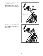
2.
Make sure that the iFit Live module is inserted
in the console.
To use an iFit Live workout, make sure that the iFit
Live module is inserted in the console.
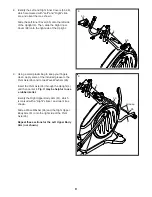
3. Select the iFit Live mode.
To select the iFit Live mode, press the iFit Live
button.
4. Select a user.
If more than one user is registered with your iFit.
com membership, you can switch users in the iFit
Live main screen. Press the increase and decrease
buttons next to the Enter button to select a user.
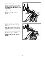
5. Select an iFit Live workout.
To select an iFit Live workout, press one of the
iFit Live buttons. Note: Before some workouts will
download, you must go to www.iFit.com and add
them to your schedule.
Press the iFit Live button to download the next
workout in your schedule. Press the My Trainer
button, the My Maps button, the World Tour but-
ton, or the Event Training button to download the
next workout of that type in your schedule. Press
the Compete button to compete in a race that you
have previously scheduled.
For more information
about the iFit Live workouts, please see
www.iFit.com.
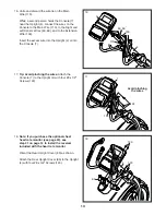
When you select an iFit Live workout, the dis-
play will show the duration of the workout and the
approximate number of calories you will burn. The
display may also show the name of the workout. If
you select a competition workout, the display may
count down to the beginning of the race.
6. Start the workout.
See step 3 on page 21.
During some workouts, the voice of a personal
trainer will guide you through your workout. You
can select an audio setting for your personal trainer
(see HOW TO CHANGE CONSOLE SETTINGS on
page 24).
To stop the workout at any time, stop pedaling. The
time will flash in the display. To resume the work-
out, simply resume pedaling.


